background image


Some Safety Measures 


Important Precautions 

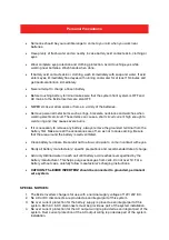
The output side of the AC wiring of Exide Inverterz should never be connected to 
utility power or a DG set. This condition is far worse than a short circuit. If the unit 
survives this condition, it will shut down until connections are made. 

Installation should ensure that the AC output of Exide Inverterz should not be 
connected to AC input. 

Note:  Connecting the battery cables to the Exide Inverterz battery terminals 
may cause spark, usually accompanied by a “snap”. This is normal, don’t let it 
scare you. 

Never disconnect battery cables while the Exide Inverterz is delivering power 
or battery charger is operating. Always turn the switch off first. 


General Precautions 


Before installing, connecting any wiring or using the Exide Inverterz, read all instructions 
of this instruction manual. 


CAUTION

: Do not install or connect batteries to this unit unless instructed to do so. 

Failure to comply with this instruction can cause damage or complete failure of the unit.


CAUTION: 

To reduce risk of injury, use only deep-cycle lead acid batteries.


Do not expose the system to rain, snow or liquids of any type. Do not disassemble the 
system; call EXIDE authorised service centre when service or repair is required. In 
correct reassembly may result in a risk of electric shock or fire. 


To reduce risk of electric shock, disconnect all the wiring from the system before 
attempting any maintenance cleaning. Turning off the system will not reduce this risk 


WARNNING:

 WORKING IN VICINITY OF A LEAD ACID BATTERY IS DANGEROUS. 


Be extra cautious when working with metal tools on, or around batteries. The potential 
exists to drop a tool and short-circuit the batteries or other electrical parts resulting in 
sparks that could cause an explosion 


Do not leave batteries in discharge state for more than a day or two. They will undergo a 
chemical process called sulfation which can permanently damage the battery. Also 
batteries will self-discharge over a period of 3-6 months, so they should periodically 
recharge even if they are not being used. 


GROUNDING INSTRUCTIONS:

 The Exide Inverterz should be connected to a 

grounded, permanent wiring system. 

Содержание Inverterz Magic 12V 1050VA

Страница 1: ...USER MANUAL EXIDE INVERTERZ For any service related issue call our Toll Free No 1800 103 5454 Exide Industries Ltd 59E Chowringhee Road Kolkata 700 020 ...

Страница 2: ...al Fast Charging Rates through Touch Switch LED Indications for better user interface Automatic Overload Battery Low Over Temperature Short Circuit protection sense Wide Mains Voltage Charging Range i e 100V 290V Mains Low Voltage Charging Facility Manual Mains Bypass Facility Great Power Saving Easy to Service No Humming Noise This manual provides you thorough understanding of your Exide Inveterz...

Страница 3: ...uous glow with beep sound Battery Voltage Low Continuous glow without beep sound Battery Voltage Low Cut CHARGING CHARGED Blinking Battery Charging Continuous Glow Battery Charged OVERLOAD SHORT CIRCUIT Blinking with beep sound Overload Alarm Blinking without beep sound Shutdown Continuous glow with beep sound Short Circuit ON OFF ON ON OFF Switch LED Glow Inverterz ON ON OFF OFF ON OFF Switch LED...

Страница 4: ...wer cord to connect with mains supply Red coloured battery wire is to be connected to positive terminal of battery and black coloured wire to be connected to negative terminal of the battery Manual Bypass switch if Inverterz faulty than select Bypass selection Caution Do not reverse the battery connections it will blow the DC fuse connected in series with battery connection inside the Power Card ...

Страница 5: ...ete failure of the unit CAUTION To reduce risk of injury use only deep cycle lead acid batteries Do not expose the system to rain snow or liquids of any type Do not disassemble the system call EXIDE authorised service centre when service or repair is required In correct reassembly may result in a risk of electric shock or fire To reduce risk of electric shock disconnect all the wiring from the sys...

Страница 6: ...ded terminal from the battery first Make sure all the accessories are off so as not to cause arcing Be sure that the area around the battery is well ventilated Clean battery terminals Be careful not to allow corrosion to come in contact with eyes Study all battery manufacturers specific precautions and recommended rate of charge Add only distilled water in each cell until battery acid reaches leve...

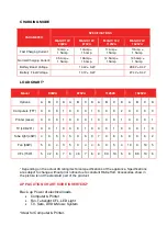
Страница 7: ... 0 1 0 0 0 1 0 0 0 2 0 0 0 3 Printer Laser 0 0 0 1 0 0 0 1 0 0 0 1 0 0 0 1 TV LCD 26 0 0 1 0 0 0 1 0 0 0 1 0 0 0 1 0 Tube light 40W 4 0 5 3 5 0 6 3 7 0 8 6 9 0 8 2 Fan 80W 5 0 4 3 5 0 4 4 6 0 5 4 10 0 10 5 CFL 15W 5 42 6 7 6 46 7 6 9 60 10 6 9 86 10 6 Depending on the actual VA rating technical specifications of the appliance Specifications are subject to change without prior notice due to constan...

Страница 8: ...rtment which are storing flammable liquids such as gasoline e Close to battery Install the system as close to the battery as possible in order to minimise the length of cable required to connect the system to the battery It is better and cheaper to run longer AC wires than longer DC cables CAUTIONS To prevent fire do not cover or obstruct ventilation openings Do not install the system in a zero cl...

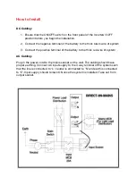
Страница 9: ...m 3 Connect the positive terminal of the battery to the thick red wire of system AC Cabling Plug in the power cord to the mains socket on the wall The cabling should have proper earthing Connect AC input supply to the 3 way terminal of the system such that the line is connected to L neutral is connected to N and earth is connected to E Input supply should remain ON once the system is installed Tak...

Страница 10: ...ystem should also work at this point since a portion of the AC power is passed through this Exide Inverterz to power the loads 4 Disconnect the AC power the system should transfer to battery mode immediately This will be indicated by clicking sound as the internal transfer relay changes position 5 The system will begin to take power from the batteries and use it to power the load And the load cont...

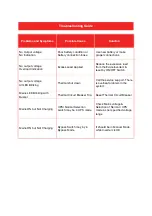
Страница 11: ...witch No output voltage All LED Blinking Thermal shut down Call the service support There is overheat problem in the system Mains LED Blinking with Buzzer Thermal Circuit Breaker Trip Reset Thermal Circuit Breaker Mains ON but Not Charging UPS Normal Selection switch may be in UPS mode Check Mains voltage Selection of Normal UPS mode as per specified voltage range Mains ON but Not Charging Bypass ...

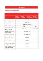
Страница 12: ...re Wave Nominal Battery Voltage 12V 24V Battery Low Cut Off 10 5V 0 2V 21 0V 0 4V Mains Input Voltage Range at Normal Mode 100V 290V 10V Mains Input Voltage Range at UPS Mode 180V 265V 10V Changeover Time Mains to Back up UPS Mode 10 msec Changeover Time Back up to Mains UPS Mode 10 msec Changeover Time Mains to Back up Normal Mode 40 msec Changeover Time Back up to Mains Normal Mode 10 msec Speci...

Отзывы: