


Table Of Contents
Installation Considerations �������������������������������������������������������������������������������������3
6 Pin Main Wire Harness ������������������������������������������������������������������������������������������3
Red & Red/White Wires - Constant Power (+) Input ���������������������������������������������� 3
Pink Wire - Ignition #1 (+) Input/Output ����������������������������������������������������������������� 3
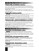
Orange Wire - Accessory (+) Output ���������������������������������������������������������������������� 4
Violet Wire - Start (+) Output ���������������������������������������������������������������������������������4
Pink/White Wire - Ign#2/Programmable (+) Output ���������������������������������������������� 4
14 Pin Secondary Wire Harness ������������������������������������������������������������������������������4
Black Wire - System Ground (-) Input �������������������������������������������������������������������� 4
Orange Wire - Status/Anti-grind (-) Output ������������������������������������������������������������ 4
Brown/Red Wire - Brake Pedal (+) Input ��������������������������������������������������������������� 4
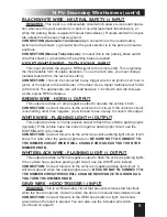
Black/White Wire - Neutral Safety (-) Input ������������������������������������������������������������ 5
Violet/White Wire - Tach Signal Input ��������������������������������������������������������������������� 5
Brown Wire - Horn (-) Output ���������������������������������������������������������������������������������5
White Wire - Flashing Light (+) Output ������������������������������������������������������������������ 5
White/Black Wire - Flashing Light (-) Output���������������������������������������������������������� 5
Gray Wire - Hood Trigger (-) Input ������������������������������������������������������������������������� 5
Wiring Overview �������������������������������������������������������������������������������������������������������7
14 Pin Secondary Wire Harness (cont’d) ���������������������������������������������������������������8
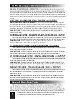
Yellow - Alarm Ignition Control (+) Output �������������������������������������������������������������� 8
White/Blue Wire - Remote Start Activation (-) Input ����������������������������������������������� 8
Lt� Green/Red Wire - OEM Alarm Arm (-) Output��������������������������������������������������� 8
Lt� Green/Black Wire - OEM Alarm Disarm (-) Output ������������������������������������������� 8
Red/White Wire - Trunk Release / CH2 (-) Output ������������������������������������������������� 8
Green & Black Data Ports ����������������������������������������������������������������������������������������8
3 Pin Satellite Relay Port (RED) ������������������������������������������������������������������������������9
3 Pin Door Lock/Unlock Port (RED) ������������������������������������������������������������������������9
Status Lights �������������������������������������������������������������������������������������������������������������9
Valet / Programming Switch ����������������������������������������������������������������������������������10
Window Mount Antenna Module ���������������������������������������������������������������������������10
Tach Programming �������������������������������������������������������������������������������������������������10
Programming Transmitters������������������������������������������������������������������������������������10
Programming Features ������������������������������������������������������������������������������������������10
Programmable Features ���������������������������������������������������������������������������������������� 11
This device complies with FCC Rules part 15� Operation is subject to the fol-
lowing two conditions, (1) This device may not cause harmful interference and,
(2) This device must accept any interference that may be received, including
interference that may cause undesired operation�
The manufacturer is not responsible for any radio or TV interference caused
by unauthorized modifications to this equipment. Such modifications could void
the user’s authority to operate the equipment.
2


