12
Instruction Manual for
Power Cooler
Air Blast
12/2
A10
Quick release coupling, coolant return from welding torch
B10
Quick release coupling, coolant supply to welding torch
C10
Viewing window (coolant level)
D10
Filler inlet coolant (with screwcap lid and sieve)
E10
Current overload cut-out for coolant pump
12.4
Commissioning
Please read the safety information on pages 3 + 4 before proceeding further
Operating environment
The working life of the cooling unit can be seriously affected, by various amounts, of Dirt, Dust,
Acids, Corrosive gases, or metallic particles being present in the air of the working environment.
Position the machine so that the Air flow into and out of the unit is completely unrestricted.
Coolant
The machine becomes from factory with a coolant-minimum filling KF23E-10 delivered.
With the coolant KF23E-10 is guaranteed antifreezes to –10 °C!
Coolant stood examine and if necassary up to the upper shop-window of the tank (C10) coolants
KF23E-10 (Article No.: if accessory see) refill.
Using a mixture of other coolants, or using a coolant other than one prescribed above will
void the manufacturers guarantee.
The filter must be in the filler rack when filling the unit.
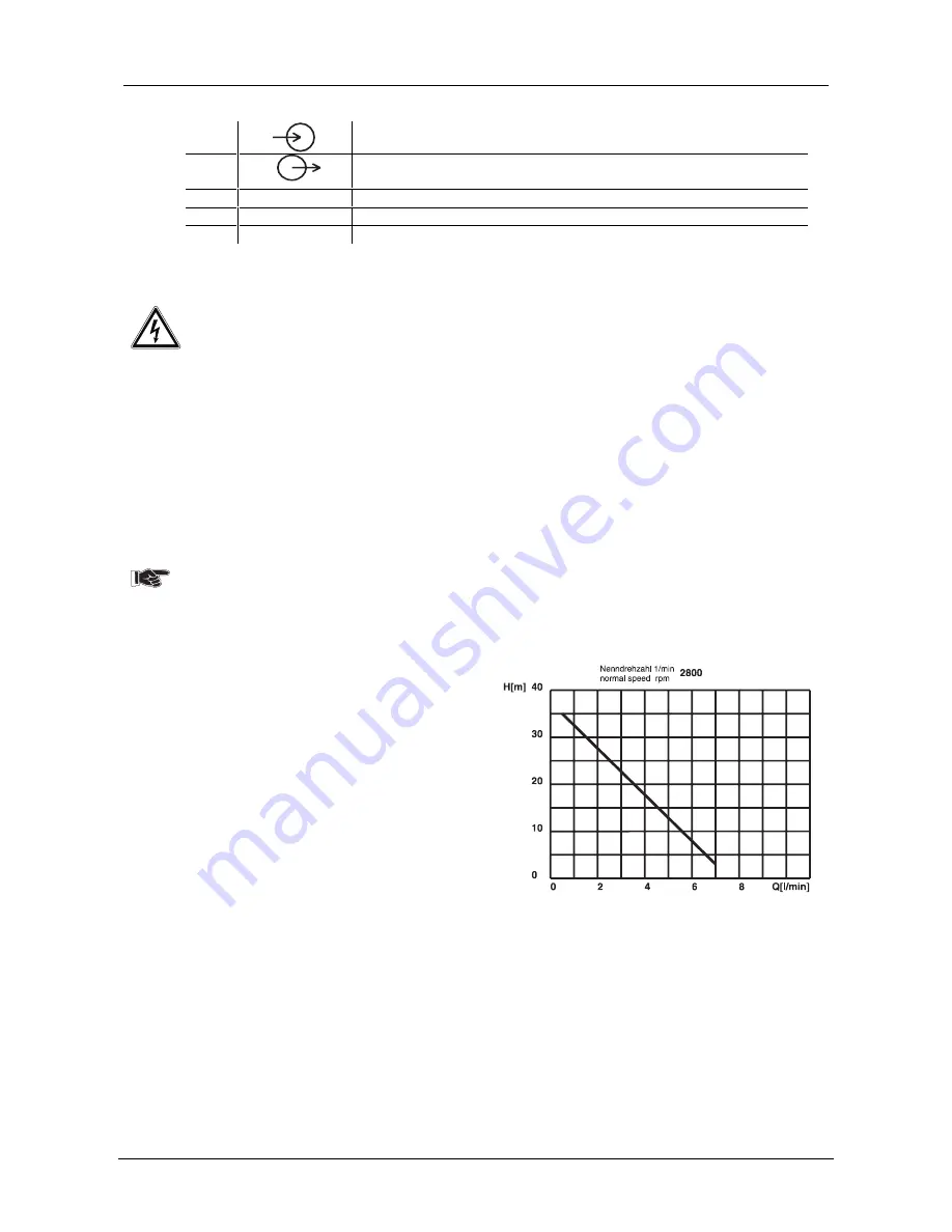
Characteristic of the integrated water pump
Putting:
H
[
in m
]
conveyor
high
P
[
in W
]
submitted pumping power
Q
[
l/min
]
conveyor
quantity
Q
[
m
3
/h
]
conveyor quantity
The power cooler is now ready for use!
Содержание inverter TIG 150 DC
Страница 46: ...13 Schaltpl ne Circuit Diagrams 13 1 13 1 inverter TIG 150 DC Schaltpl ne befinden sich ebenfalls im Ger t...
Страница 47: ...13 Schaltpl ne Circuit Diagrams 13 2 13 2 inverter TIG 200 DC powerSinus...
Страница 48: ...13 Schaltpl ne Circuit Diagrams 13 3 13 3 inverter TIG 200 DC powerSinus power K hlmodul...
Страница 49: ...13 Schaltpl ne Circuit Diagrams 13 4 13 4 inverter TIG 250 300 DC...


