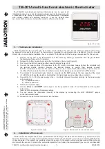
Terminal Designations
This thermostat is shipped from the factory to operate a conventional heating
and cooling system. This thermostat may also be configured for a heat pump
system. See the “heat pump” configuration step on page 17 of this manual to
configure the thermostat for heat pump applications.
Wiring
Terminal
2 Heat 2 Cool
Conventional
System
2 Heat 2 Cool
Heat Pump
System
3 Heat 2 Cool
Heat Pump
System
RC
RH
C
B
O
G
W/E
Y
Y2
W2
Transformer power
(cooling)
Transformer power
(heating)
Transformer common
Energized in heating
Energized in cooling
Fan relay
First stage of heat
First stage of cool
Second stage of cool
Second stage of heat
Transformer power
(cooling)
Transformer power
(heating)
Transformer common
Heat pump changeover
valve energized in heating
Fan relay
First stage of
emergency heat
First stage of heat & cool
Second stage of cool
Auxiliary heat relay,
second stage of heat
Heat pump changeover
valve energized in cooling
Transformer power
(cooling)
Transformer power
(heating)
Transformer common
Heat pump changeover
valve energized in heating
Fan relay
First stage of
emergency heat
First stage of heat & cool
Second stage of cool
& second stage of heat
Auxiliary heat relay,
third stage of heat
Heat pump changeover
valve energized in cooling
Wiring
Caution:
Electrical Hazard
All components of the control
system and the thermostat
installation must conform to
Class II circuits per the NEC Code.
Warning:
Do not overtighten terminal
block screws, as this can
damage the terminal block.
A damaged terminal block
can keep the thermostat
from fitting on the subbase
correctly or cause system
operation issues.
Installation Tip
Max Torque = 6in-lbs.
Wiring
If you are replacing a thermostat,
make note of the terminal
connections on the thermostat that
is being replaced. In some cases
the wiring connections will not be
color coded. For example, the
green wire may not be connected
to the
G
terminal.
Loosen the terminal block screws.
Insert wires then retighten the
terminal block screws.
Place nonflammable insulation into
the wall opening to prevent drafts.
1.
2.
3.
Wiring Tips
C Terminal
The C (common wire) terminal does
not have to be connected when the
thermostat is powered by batteries.
Wire Specifications
Use shielded or non-shielded 18-22
gauge thermostat wire.
Failure to disconnect the power
before beginning to install this
product can cause electrical shock
or equipment damage.
Note:
In many heat pump systems with
no emergency heat relay, a jumper
can be installed between
E
and
W2
to turn thermostat into a single
stage control for Emergency Heat
Operation.
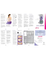
Thermostat Quick Reference
The low battery indicator is displayed when the AA battery power is low. If the user
fails to replace the battery within 21 days, the screen will only show the low battery
indicator but maintain all functionality. If the user fails to replace the batteries after
an additional 21 days (days 22-42 since first “low battery” display) the setpoints will
change to 55˚F (Heating) and 85˚F (Cooling). If the user adjusts the setpoint away from
either of these, it will hold for 4 hours then return to either 55˚F or 85˚F. After day 63
the batteries must be replaced immediately to avoid freezing or overheating because
the thermostat will shut the unit off until the batteries are changed.
Important
Indicates the current room temperature
Time and day of the week
Staging Indicators:
+1 will appear in the display when second stage of
heat or cool is on. +2 will appear for the third stage of heat.
Setpoint:
Displays the user selectable setpoint temperature.
Hold:
is displayed when the thermostat program is permanently overridden.
System Operation Indicators:
If these or the Fan indicator are flashing, it means that the system is in a
delay of some type (compressor delay, cooling fan delay, staging delay).
Low Battery Indicator:
Replace batterieswhen this indicator is shown.
Program Menu Options:
Show different options during programming.
Program Time Periods - Residential:
Uses 4 time periods - WAKE, RETURN,
LEAVE & SLEEP.
Commercial:
Uses 2 or 4 time periods that appear in the text
field - Occupied & Unoccupied.
Getting to know your thermostat
Thermostat Quick Reference
Battery Installation
Battery installation is recommended even if the thermostat is
hardwired (C terminal connected). When the thermostat is hardwired
and batteries are installed, the thermostat will activate a compressor
delay of 5 minutes when it detects a power outage from the hardwired
power supply.
Important:
High quality alkaline batteries are recommended.
Rechargeable batteries or low quality batteries
do not guarantee a 1-year life span.
Insert 2 AA Alkaline batteries
(included). High quality alkaline
batteries are recommended.
Simple operating instructions
are found on the back of the
battery door.
To release battery cover press finger bevel
on the left side and lift the cover to access
batteries.