24
www.evolutionpowertools.com
ASSEMBLY & OPERATION
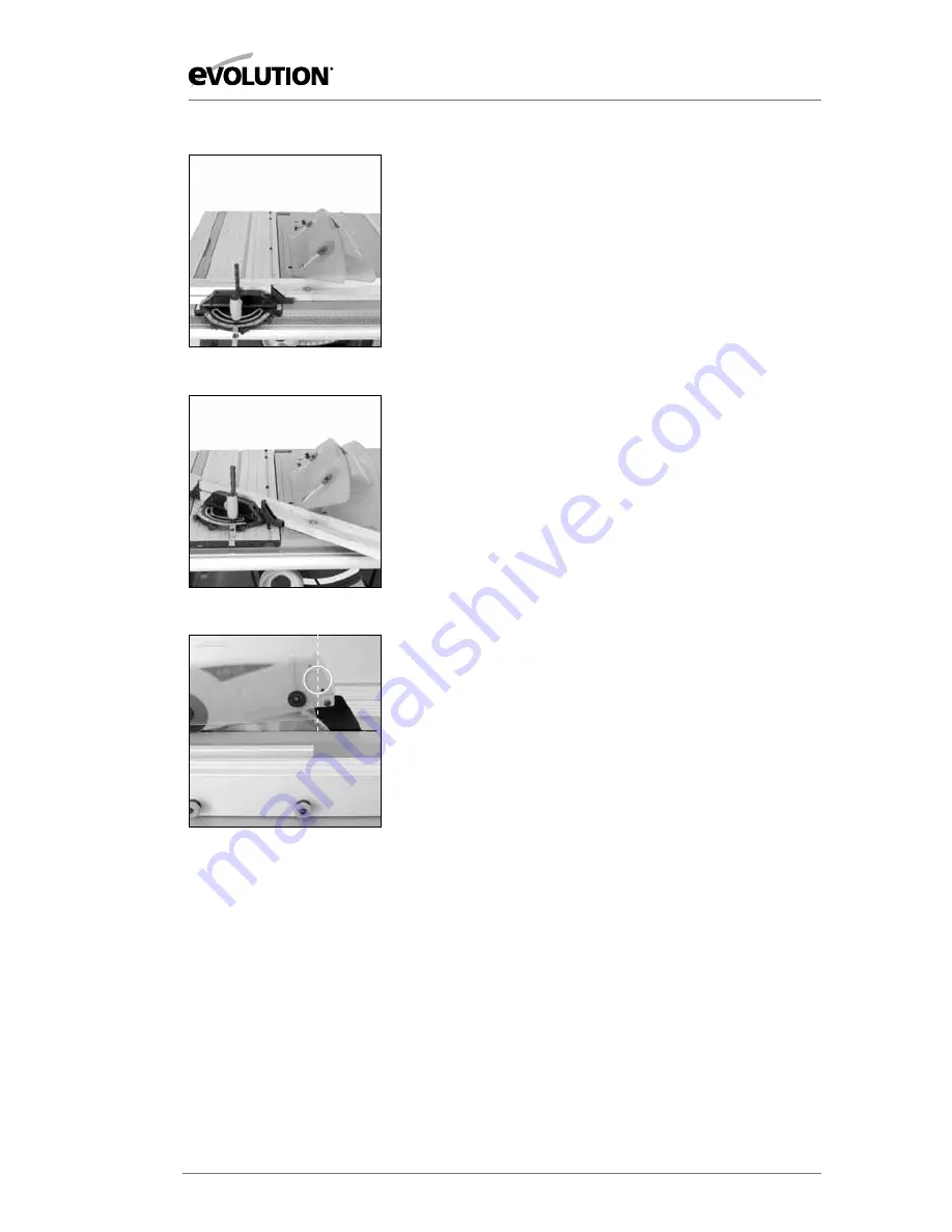
FIG. 34
FIG. 35
3. Bevel crosscutting
Bevel crosscutting is the same as crosscutting but with the
blade tilted at an angle. Tilt the blade to the desired angle as
previously described, and ensure that it is locked in place.
Set the mitre gauge to 90
0
and adjust the faceplate so that it
does not touch or foul the saw blade as it passes. Index the
material against the mitre gauge and make your cut.
(Fig. 34)
4. Compound mitre cutting
Compound mitre cutting is a combination of mitre cutting and
bevel crosscutting.
Adjust the mitre gauge and the blade to the desired angles.
Lock both in place.
Check that the mitre gauge will pass the saw blade without
fouling. Adjust the mitre gauge faceplate if necessary.
Index the material against the mitre gauge and make your cut.
(Fig. 35)
5. Repetitive crosscutting
Repetitive cutting is cutting a number of pieces to the same
length without having to mark out each piece.
Note:
Repetitive cross-cutting is carried out with the mitre
gauge positioned on the LH side of the machine, with the rip
fence on the RH side of the machine.
Caution:
The Rip Fence can be used as a length stop only if it
is properly set and adjusted.
To use the Rip Fence as length stop align the back of the
adjustable Fence Face with the back of the saw blade and set at
the required distance from the blade. This will allow clearance
for the material as it passes through the saw blade.
(Fig. 36)
•
Check that the Rip Fence is set at the required distance and is
lying parallel to the saw blade.
•
Index the material to be cut against the Mitre Gauge and the
Rip Fence Face.
•
Hold the material and Mitre Gauge with your left hand.
•
Gently push the workpiece through the saw. Use a push stick
in your right hand to guide the workpiece on the RH side of
the blade.
Note:
If the Sliding Carriage system is deployed for repetitive cross-
cutting, the Mitre Gauge must be fastened to the carriage.
We recommend that the mitre gauge be fixed in its dedicated
position to the front of the carriage, where the locking screw will
engage in a hole in the sliding carriage body.
FIG. 36


