23
www.evolutionpowertools.com
EN
ES
DE
FR
IT
NL
Note:
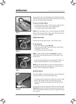
We recommend that normally the rip fence faceplate be
adjusted so that the rear of the faceplate guide is ‘in line’ with the
rear of the blade where it emerges from the table.
(Fig. 28B)
Note:
If the rip fence is used on the LH (left hand) side of the
blade, the aluminium faceplate will have to be repositioned
to the RH (right hand) side of the plastic carrier.
• Loosen the two wing nuts and slide the aluminium
faceplate from the plastic carrier.
• Remove the dome headed machine screws from the carrier.
• Reposition the faceplate to the RH side of the carrier and
re-attach using the machine screws and the wing nuts.
Adjust as necessary.
Return to the original configuration when the rip fence is in
the normal (RH) operating position.
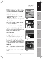
Note:
When the machine is not in use, the rip fence has dedicated
storage on the left hand side of the machine body (Fig 29).
Loosen the wing nuts and slide the rip fence base into the centre
of the rip fence faceplate and secure. Locate the mounting
brackets on the left hand side of the machine body and press the
protruding ends of the faceplate into the brackets.
THE DUAL READ SCALE
Note:
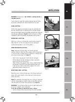
The rip fence guide incorporates a viewing window to
aid reading the measurement scale found on the fence rail.
(Fig. 30)
. The scale should be regarded as a useful guide. It is
not a substitute for careful and accurate ‘marking out’.
This machine has a dual read scale that shows the distance
from the blade to the rip fence through the viewing window.
This can be used to aid setting the cutting distance from the
blade to the rip fence. With the rip fence faceplate attached by
its shorter side, use the black scale to set the distance of the
rip fence. When the faceplate is attached by its longer side, use
the green scale.
MITRE GAUGE
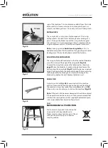
Note:
The mitre gauge
(K)
(Fig. 31)
can be used on either side
of the table and runs in either of the two inverted 'T' slots in
the table top.
Carefully slide the mitre gauge into the required slot in the
table top.
Fig. 31
Fig. 28B
Fig. 29
Fig. 30


