background image

12

www.evolutionpowertools.com

be installed in an area that provides 
enough room to easily handle the 
size of your workpiece. 

Cramped, dark 

areas, and uneven slippery floors invite 
accidents. 

d) Frequently clean and remove sawdust 

from under the saw table and/or the 
dust collection device.

 Accumulated 

sawdust is combustible and may self-ignite. 

e) The table saw must be secured.

 A table 

saw that is not properly secured may move 
or tip over. 

f) Remove tools, wood scraps, etc. from 

the table before the table saw is 
turned on. 

Distraction or a potential jam 

can be dangerous. 

g) Always use saw blades with correct 

size and shape (diamond versus round) 
of arbour holes. 

Saw blades that do not 

match the mounting hardware of the saw 
will run off-centre, causing loss of control. 

h) Never use damaged or incorrect 

saw blade mounting means such as 
flanges, saw blade washers, bolts 
or nuts. 

These mounting means were 

specially designed for your saw, for safe 
operation and optimum performance. 

i) Never stand on the table saw, do not 

use it as a stepping stool. 

Serious injury 

could occur if the tool is tipped or if the 
cutting tool is accidentally contacted. 

j) Make sure that the saw blade is 

installed to rotate in the proper 
direction. Do not use grinding wheels, 
wire brushes, or abrasive wheels 
on a table saw. 

Improper saw blade 

installation or use of accessories not 
recommended may cause serious injury.

(4.1)

GETTING STARTED 

UNPACKING

Caution: 

This packaging contains sharp 

objects. Take care when unpacking.   
Remove the machine, together with the 
accessories supplied from the packaging. 
Check carefully to ensure that the machine 
is in good condition and account for all the 
accessories listed in this manual. Also make 
sure that all the accessories are complete.  
If any parts are found to be missing,  
the machine and its accessories should be 
returned together in their original packaging 
to the retailer. Do not throw the packaging 
away; keep it safe throughout the guarantee 
period. Dispose of the packaging in an 
environmentally responsible manner.   
Recycle if possible. Do not let children  
play with empty plastic bags due to the  
risk of suffocation.

Содержание FURY5-S

Страница 1: ...FURY5 S Original written in UK English Date Published 15 03 2019 Original Instructions Original Anweisungen ...

Страница 2: ...ge 16 Attaching the Table Extensions Page 17 The Fence Rail Page 18 Adjustment Page 18 Checking Adjusting the Rip Fence Page 19 Sliding Mitre Gauge Page 19 Top Blade Guard Page 20 OPERATION Page 21 On Off Safety Switch Page 21 Raising Lowering the Blade Page 21 Tilting the Blade Page 22 Rip Fence Guide Page 22 Dual Read Scale Page 23 Mitre Gauge Page 23 Anti Bounce Device Page 24 Basic Table Saw O...

Страница 3: ...ghout our worldwide organization but technical help is also available from your supplier WEB www evolutionpowertools com 1 4 Congratulations on your purchase of an Evolution Power Tools machine Please complete your product registration online as explained in the A4 online guarantee registration leaflet included with this machine You can also scan the QR code found on the A4 leaflet with a smart ph...

Страница 4: ...5 64 Speed No Load 3250min 1 3250rpm Weight 20 14kg 44 4lbs CUTTING CAPACITY METRIC IMPERIAL Maximum depth of cut at 90 85mm 3 1 4 Maximum depth of cut at 45 65mm 2 1 2 Mild Steel Plate Optimal Cutting Thickness 3mm 1 8 Mild Steel Box Section Opt Wall Thickness 3mm 1 8 Rip Capacity Right Of The Blade 400mm 15 3 4 In BLADE METRIC IMPERIAL Diameter 255mm 10 Bore 25 4mm 1 Number of Teeth 24 24 Kerf 2...

Страница 5: ... BS EN ISO 5349 2 2002 Many factors can influence the actual vibration level during operation e g the work surfaces condition and orientation and the type and condition of the machine being used Before each use such factors should be assessed and where possible appropriate working practices adopted Managing these factors can help reduce the effects of vibration Handling Handle the machine with car...

Страница 6: ...hine can be used to cut Mild Steel Max Thickness 3mm Aluminium Max Thickness 3mm Wood and wood based materials Max Thickness 85mm Note Cutting galvanised steel may reduce blade life 1 11 PROHIBITED USE OF THIS POWER TOOL WARNING This product is a table saw and must only be used as such It must not be modified in any way or used to power any other equipment or drive any other accessories other than...

Страница 7: ...refers to your mains operated corded power tool or battery operated cordless power tool 2 2 1 General Power Tool Safety Warnings Work area safety a Keep work area clean and well lit Cluttered or dark areas invite accidents b Do not operate power tools in explosive atmospheres such as in the presence of flammable liquids gasses or dust Power tools create sparks which may ignite the dust or fumes c ...

Страница 8: ...cted and properly used Use of dust collection can reduce dust related hazards 2 5 4 General Power Tool Safety Warnings Power tool use and care a Do not force the power tool Use the correct power tool for your application The correct power tool will do the job better and safer at a rate for which it was designed b Do not use the power tool if the switch does not turn it on or off Any power tool tha...

Страница 9: ...asses with side shield or a full face shield where necessary ADDITIONAL SAFETY INSTRUCTIONS TABLE SAWS 1 Guarding related warnings a Keep guards in place Guards must be in working order and be properly mounted A guard that is loose damaged or is not functioning correctly must be repaired or replaced b Always use saw blade guard riving knife and anti kickback device for every through cutting operat...

Страница 10: ...nd from the saw blade f Never use a damaged or cut push stick A damaged push stick may break causing your hand to slip into the saw blade g Do not perform any operation freehand Always use either the rip fence or the mitre gauge to position and guide the workpiece Freehand means using your hands to support or guide the workpiece in lieu of a rip fence or mitre gauge Freehand sawing leads to misali...

Страница 11: ...hat can cause kickback g Support large panels to minimise the risk of saw blade pinching and kickback Large panels tend to sag under their own weight Support s must be placed under all portions of the panel overhanging the table top h Use extra caution when cutting a workpiece that is twisted knotted warped or does not have a straight edge to guide it with a mitre gauge or along the fence A warped...

Страница 12: ...rformance i Never stand on the table saw do not use it as a stepping stool Serious injury could occur if the tool is tipped or if the cutting tool is accidentally contacted j Make sure that the saw blade is installed to rotate in the proper direction Do not use grinding wheels wire brushes or abrasive wheels on a table saw Improper saw blade installation or use of accessories not recommended may c...

Страница 13: ...Bounce Device 1 Adjustable Rip Fence 1 Rear Cantilever Braces 2 Push Stick 1 Fence Rail 2 piece 1 Fence Rail Joining Tongue 1 Hex Key 1 Blade Changing Spanners 2pc 1 Set Assorted fixings 1 Bag Riving Knife 1 4 3 ADDITIONAL ACCESSORIES In addition to the standard items supplied with this machine the following accessories are also available from the Evolution online shop at www evolutionpowertools c...

Страница 14: ...ING KNIFE 3 BLADE GUARD 4 BLADE 5 BEVEL LOCKING KNOB 6 RISE AND FALL BEVEL ADJUSTMENT HAND WHEEL 7 RIP FENCE SCALE MAGNIFIER 8 RIP FENCE LOCKING HANDLE 9 PUSH STICK 10 RIP FENCE 11 REAR CANTILEVER BRACES 12 ANTI BOUNCE DEVICE 13 SLIDING MITRE FENCE 14 DUST PORT 15 DUST HOSE 16 REAR DUST PORT 17 BLADE CHANGE SPANNERS ...

Страница 15: ...x 4 F SIDE TABLE EXTENSION PANELS x 2 G SIDE TABLE SUPPORT STRUTS x 4 H BLADE GUARD x 1 I ANTI BOUNCE DEVICE x 1 J RIP FENCE x 1 K MITRE GAUGE x 1 L FENCE RAIL 2 pieces M FENCE RAIL JOINING TONGUE x 1 N HEX HEADED SCREW x 28 O FLANGE NUT x 35 P COACH BOLT BLACK x 7 Q HEX SOCKET CAP SCREW x 1 R NUT BLACK x 2 S RIVING KNIFE x 1 WHAT S IN THE BOX H I J N O P Q R A E B C D K F G M L T S ...

Страница 16: ... work surface Fig 2 Note A large clean cloth positioned on the work surface would help protect the table top from accidental damage Remove the eight Ø10 mm hex headed screws and their associated washers from the corners of the machines main body Fig 3 Attach the four legs A to the main body of the machine using the previously removed hex headed screws Do not tighten the screws at this stage Hand t...

Страница 17: ...ension panels F are not handed and can fit on either side of the machine Each table extension attaches to the main table of the machine using two hex headed machine screws N and nut O The holes for the screws to pass through in the table extension panels are positioned to the very front and rear of the side flanges Fig 7 Insert the hex headed machine screws and attach the table extension panels to...

Страница 18: ...g tongue M should be inserted into the rectangular voids in the two extrusions to bridge both parts of the Fence Rail Fig 10 Attach the seven coach bolts P within the seven holes of the machine two in each extension and three in the main aluminium table using nut O Hand tighten only Fig 11 Slide the fence rail over the seven protruding bolt heads Fig 12 until the fence rail is central across the f...

Страница 19: ... up to the straight edge and check for parallelism If adjustment is needed gain access to the two socket headed screws through the two holes in the carrier Fig 14 Loosen these screws using the correct sized hex key and adjust the fence as required Tighten and re check the rip fence when correct alignment has been achieved Lower the blade SLIDING MITRE GAUGE Note The sliding mitre gauge K fits in e...

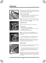
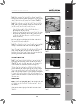
Страница 20: ...d mounting block Fig 18 Ensure that the mounting blocks projecting lugs engage with the slot in the Riving Knife Adjust the Riving Knife so that it is between 3 5mm from the saw blade The blade guard mounting hole on the riving knife should be at least 10mm higher than the tooth peak Fig 19 When correct alignment is achieved tighten the fixing bolt Check the saw blade rotates freely and teeth are ...

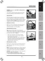
Страница 21: ... a machine is connected to this Table Saw follow the Instructions provided by the supplier manufacturer of the dust extraction equipment Use of such equipment will ensure that the workplace is kept clean and tidy and that dust is kept to a minimum OPERATION ON OFF SAFETY SWITCH WARNING Before operating the switch make sure that the blade guard is correctly installed and operating properly Push the...

Страница 22: ...d wheel to tilt the blade Note A protractor scale and pointer Fig 27 are readily visible allowing the operator to quickly set the blade to the desired angle When the desired angle has been achieved the tilt locking knob should be tightened to secure the blade angle Note We recommend that when any tilt cutting operation is concluded that the blade be returned to its normal vertical setting and the ...

Страница 23: ... nuts and slide the rip fence base into the centre of the rip fence faceplate and secure Locate the mounting brackets on the left hand side of the machine body and press the protruding ends of the faceplate into the brackets THE DUAL READ SCALE Note The rip fence guide incorporates a viewing window to aid reading the measurement scale found on the fence rail Fig 30 The scale should be regarded as ...

Страница 24: ...ency and secure in place using the thumb screws Adjust the anti bounce device so that the head does not quite touch the material to be cut You can achieve this by gently clamping the material to be cut with the anti bounce device and then backing off the head by 1 2 to 1 turn Note When the machine is not in use the mitre gauge anti bounce device has dedicated storage on the right hand side of the ...

Страница 25: ... the vertical and the mitre gauge is set to an angle A compound cut is therefore a combination of a mitre cut and a bevel cut Fig 37 Adjust the mitre gauge and set to the desired angle Tilt the blade to the desired angle and lock in place by tightening the tilt locking knob Check that the mitre gauge will pass the saw blade without any interference Adjust the mitre gauge faceplate if necessary Ind...

Страница 26: ...ines table Fig 40 The mitre gauge is not required for this operation and should be stored safely off the machine for future use WARNING Check that the rip fence is locked in position and is parallel to the saw blade Check that the riving knife is properly aligned with the saw blade When ripping small section material a push stick should be used to feed guide the final 300mm of the material past th...

Страница 27: ...spanners provided One spanner will fit the hexagonal nut machined onto the outer blade flange and thus prevent the arbor from rotating The other spanner will fit the arbor nut Fig 44 Remove the arbor nut the outer blade flange and the blade Thoroughly clean any debris from these parts and also from the exposed motor arbor and inner blade flange The inner blade flange can be left in situ Fit the ne...

Страница 28: ...ving knife remove the table insert as shown on page 21 raise the blade to its maximum height and loosen the bolt securing the riving knife Fig 47 with the spanner supplied Adjust the riving knife to the correct distance of 3 5mm ensuring the fixing hole for the blade guard is level with the top of the blade and re tighten the bolt Replace the table insert PUSH STICK A plastic push stick Fig 48 is ...

Страница 29: ...2015 863 EU Substances in Electrical Equipment RoHS Directive 2012 19 EU The Waste Electrical and Electronic Equipment WEEE Directive And is in conformity with the applicable requirements of the following documents EN 62841 1 2015 EN 62841 3 1 2014 A11 2017 EN 55014 1 2017 EN55014 2 2015 EN61000 3 2 2014 EN61000 3 3 2013 Product Details Description FURY5 S 255mm 10 MULTI MATERIAL CUTTING TABLE SAW...

Страница 30: ...MONTAGE Seite 43 Das Gestell Seite 43 Montieren der Tischverlängerungen Seite 44 Die Anschlagschiene Seite 45 Einstellung Seite 46 Prüfen Einstellen des Längsanschlags Seite 46 Schlittengehrungslehre Seite 47 Oberer Sägeblattschutz Seite 47 BETRIEB Seite 49 Ein Aus Sicherheitsschalter Seite 49 Heben Senken des Sägeblatts Seite 49 Kippen des Sägeblatts Seite 50 Längsanschlagführung Seite 50 Gehrung...

Страница 31: ...tweiten Organisation aber sie erhalten Technische Hilfe auch von Ihrem Lieferanten WEB www evolutionpowertools com 1 4 Glückwunsch zum Kauf einer Maschine von Evolution Power Tools Bitte füllen Sie Ihre Produktregistrierung online wie es in der A4 Broschüre zur Online Garantieregistrierung erklärt ist die dieser Maschine beiliegt Sie können auch den QR Code der sich auf der A4 Broschüre befindet m...

Страница 32: ...n 1 3250 rpm Gewicht 20 14kg 44 4lbs SCHNITTLEISTUNG METRISCH BRITISCHE EINHEITEN Maximale Tiefe für einen Schnitt bei 90 85 mm 3 1 4 MaximaleTiefe für einen Schnitt bei 45 65 mm 2 1 2 Baustahlblech Optimale Schneiddicke 3 mm 1 8 Baustahl Kastenprofil Opt Schneiddicke 3 mm 1 8 Schneidleistung Recht der Klinge 400mm 15 3 4 In SÄGEBLATT METRISCH BRITISCHE EINHEITEN Durchmesser 255 mm 10 Bohrung 25 4...

Страница 33: ...Vibrationsniveau beeinflussen z B der Zustand und die Orientierung der Bearbeitungsflächen und die Art und der Zustand der verwendeten Maschine Solche Faktoren können vor jeder Verwendung beurteilt werden und wenn erforderlich können entsprechende Arbeitsrichtlinien umgesetzt werden Eine Kontrolle dieser Faktoren kann dabei helfen die Auswirkungen der Vibrationen zu reduzieren Handhabung Gehen Sie...

Страница 34: ...ts verkürzen 1 11 VERBOTENE VERWENDUNG DIESES ELEKTROWERKZEUGS WARNUNG Dieses Produkt ist eine Tischsäge und darf nur als solche verwendet werden Es darf in keinster Weise modifiziert oder zum Antrieb anderer Geräte verwendet werden oder irgendwelches anderes Zubehör antreiben als solches das in dieser Bedienungsanleitung erwähnt ist 1 13 WARNUNG Dieses Gerät ist nicht dafür geeignet dass es von P...

Страница 35: ...gen Funken die den Staub oder die Dämpfe entzünden können c Halten Sie Kinder und andere Personen während der Benutzung eines Elektrowerkzeugs fern Bei Ablenkung können Sie die Kontrolle über das Gerät verlieren 2 3 2 Allgemeine Sicherheitswarnungen für Elektrowerkzeuge Elektrische Sicherheit a Der Anschlussstecker des Geräts muss in die Steckdose passen Der Stecker darf in keiner Weise verändert ...

Страница 36: ...zen Sie kein Elektrowerkzeug dessen Ein Aus Schalter defekt ist Ein Elektrowerkzeug das sich nicht mehr ein oder ausschalten lässt ist gefährlich und muss repariert werden c Trennen Sie das Elektrowerkzeug von der Steckdose bzw nehmen Sie den Akku aus dem Elektrowerkzeug bevor Sie Geräteeinstellungen vornehmen Zubehörteile wechseln oder das Elektrowerkzeug verstauen Diese Vorsichtsmaßnahmen verhin...

Страница 37: ...ern c Befestigen Sie die Schutzvorrichtung unmittelbar nach Abschluss des Schnitts erneut wie Falz Nut oder Neuschnitte für welche die Vorrichtung der Spaltkeil und oder die Rückschlagsicherung abgenommen werden müssen Die Vorrichtung der Spaltkeil und die Rückschlagsicherung mindern das Verletzungsrisiko d Stellen Sie sicher dass das Sägeblatt nicht die Schutzvorrichtung den Spaltkeil oder das We...

Страница 38: ...e Die Blockade des Sägeblattes durch das Werkstück kann zu Ausschlagen oder zum Stillstand des Motors führen k Entfernen Sie keine Stücke von Schnittmaterial während die Säge läuft Das Material kann zwischen dem Anschlag oder innerhalb des Sägeblattschutzes eingeschlossen sein sodass das Sägeblatt Ihre Finger in das Sägeblatt ziehen könnte Schalten Sie die Säge aus und warten Sie bis das Sägeblatt...

Страница 39: ...ln oder Einstellungen am Spaltkeil der Rückschlagsicherung oder dem Sägeblattschutz vornehmen und wenn die Maschine unbeaufsichtigt bleibt Durch Vorsichtsmaßnahmen können Unfälle vermieden werden b Lassen Sie die Tischsäge niemals unbeaufsichtigt laufen Schalten Sie sie aus und lassen Sie das Werkzeug nicht unbeaufsichtigt bis es vollständig zum Stillstand kommt Eine unbeaufsichtigte laufende Säge...

Страница 40: ... Wiederverwertung zu Lassen Sie auf Grund der Erstickungsgefahr keine Kinder mit leeren Plastikbeuteln spülen 4 2 ITEMS SUPPLIED Beschreibung Menge Bedienungsanleitung 1 Vielzwecksägeblatt 1 Tischverlängerungen 2 Tischverlängerungs Stützstreben 4 Fußsatz 4 Eckfüße 1 Satz Querstreben 4 Gummifüße 4 Oberer Sägeblattschutz mit Absauganschluss 1 Staubabsaugschlauch 1 Gehrungslehre 1 Antiprellvorrichtun...

Страница 41: ...4 SÄGEBLATT 5 NEIGUNGS BEFESTIGUNGSGRIFF 6 AUFUNDAB NEIGUNGSEINSTELLUNGS HANDRAD 7 LÄNGSANSCHLAG SKALENLUPE 8 LÄNGSANSCHLAG BEFESTIGUNGSGRIFF 9 HANDGRIFF 10 LÄNGSANSCHLAG 11 HINTERE KONSOLENKLEMMEN 12 ANTIPRELLVORRICHTUNG 13 SCHLITTENGEHRUNGSLEHRE 14 ENTSTAUBUNGSANSCHLUSS 15 ENTSTAUBUNGSSCHLAUCH 16 HINTERER ENTSTAUBUNGSANSCHLUSS 17 SCHLÜSSEL FÜR SÄGEBLATTWECHSEL ...

Страница 42: ...ERUNGSPLATTEN x 2 G SEITLICHE TISCHSTÜTZSTREBEN x 4 H SÄGEBLATTSCHUTZ x1 I ANTIPRELLVORRICHTUNG x 1 J LÄNGSANSCHLAG x 1 K GEHRUNGSLEHRE x 1 L ANSCHLAGSCHIENE 2 Stück M ANSCHLAGSCHIENEN VERBINDUNGSZUNGE x 1 N SECHSKANTSCHRAUBE x 28 O FLANSCHMUTTER x 35 P SCHLOSSSCHRAUBE SCHWARZ x 7 Q INNENSECHSKANTSCHRAUBE x 1 R MUTTER SCHWARZ x 2 S SPALTKEIL x 1 WHAT S IN THE BOX H I J N O P Q R A E B C D K F G M ...

Страница 43: ...r Tischoberseite auf der Arbeitsfläche Abb 2 Hinweis Ein großes sauberes Tuch auf der Arbeitsfläche hilft beim Schutz des Tischs vor versehentlicher Beschädigung Entfernen Sie die acht 10 mm Sechskantschrauben und ihre zugehörigen Scheiben von den Ecken des Maschinenhauptteils Abb 3 Bringen Sie die vier Füße A am Hauptteil der Maschine mit den zuvor entfernten Sechskantschrauben an Ziehen Sie zu d...

Страница 44: ...b ist MONTIEREN DER TISCHVERLÄNGERUNGEN Hinweis Die Tischverlängerungsplatten aus Pressstahl F sind nicht seitengebunden und können an jeder Seite der Maschine angebracht werden Jede Tischverlängerung wird am Haupttisch der Maschine mit zwei Sechskantschrauben N und Mutter O angebracht Die Bohrungen zum Durchführen der Schrauben in den Tischverlängerungsplatten ganz vorne und hinten von den Seiten...

Страница 45: ...rreicht ist sind alle Befestigungsschrauben fest anzuziehen DIE ANSCHLAGSCHIENE Hinweis Die Anschlagschiene wird in zwei zusammensteckbaren Stücken geliefert L Die Verbindungszunge aus Kunststoff M ist in die rechteckigen Hohlräume in den beiden Profilen einzustecken um die beiden Teile der Anschlagschiene zu verbinden Abb 10 Befestigen Sie die sieben Schlossschrauben P in den sieben Bohrungen der...

Страница 46: ...verriegelt werden indem der Hebel nach unten gedrückt wird PRÜFEN EINSTELLEN DES LÄNGSANSCHLAGS Wenn die Anschlagschiene und der Längsanschlag an der Maschine angebracht wurden sollte der Längsanschlag geprüft werden um sicherzustellen dass er parallel zum Sägeblatt liegt Heben Sie das Sägeblatt ganz nach oben Legen Sie ein Lineal oder ähnliches gegen das Sägeblatt Bringen Sie den Längsanschlag na...

Страница 47: ... Abb 17 OBERER SÄGEBLATTSCHUTZ Der obere Sägeblattschutz H manchmal Kronenschutz genannt muss immer am Spaltkeil der Maschine angebracht sein Die Teilungs Linie entlang der Oberseite des Sägeblattschutz zeigt die Mittellinie des Sägeblatts darunter an Die Grafik am Sägeblattschutz verstärkt die Schnittlinie des Sägeblatts zusätzlich WARNUNG Der obere Sägeblattschutz muss angebracht sein am Spaltke...

Страница 48: ...lattschutz Wenn Sie verifiziert haben dass der Sägeblattschutz über den gesamten Höheneinstellungsbereich des Sägeblatts funktioniert prüfen Sie ob der Sägeblattschutz genauso gut funktioniert wenn das Sägeblatt auf einen Winkel eingestellt ist Prüfen Sie ob der Sägeblattschutz bei vollständig abgesenktem Sägeblatt die Tischoberfläche berührt Hinweis Der obere Sägeblattschutz ist mit einem Staubab...

Страница 49: ...Abb 24 In seiner normalen äußeren Position wird dieses Handrad zum Heben und Senken des Sägeblatts verwendet Wenn das Handrad gegen seine Spannfeder hineingedrückt wird rastet ein Zahnrad in eine gebogene Zahnstange im Hauptteil der Maschine ein Damit kann das Handrad zum Einstellen des Neigungswinkels des Sägeblatts verwendet werden Zum Heben oder Senken des Sägeblatts Stellen Sie sicher dass sic...

Страница 50: ...zum Arretieren nach unten und ziehen Sie zum Lösen nach oben Üben Sie keine übermäßige Kraft auf den Arretiergriff aus Drücken Sie den Griff mit Ihrer Handfläche sanft nach unten bis der Griff einrastet Hinweis Die Längsanschlagführung beinhaltet eine Lupe Abb 28A zur Erleichterung der Ablesung der Messskala an der Anschlagführung Hinweis Wir empfehlen die Längsanschlagplatte so einzustellen dass ...

Страница 51: ...inge zu Parallelanschlag anzeigt Dies kann dabei helfen die Schneiddistanz von Klinge bis Parallelanschlag einzustellen Ist die Aufspannplatte des Parallelanschlags an der kürzeren Seite angebracht verwenden Sie die schwarze Maßeinheit um die Distanz bis zum Parallelanschlag zu messen Ist die Aufspannplatte an der längeren Seite angebracht verwenden Sie die grüne Maßeinheit GEHRUNGSLEHRE Hinweis D...

Страница 52: ...inen speziellen Stauraum auf der rechten Seite des Maschinengehäuses Abb 34 Heben Sie die Rücklaufsperre an und drehen Sie sie gegen den Uhrzeigersinn bis sie sich neben dem Knopf der Gehrungssperre befindet und senken Sie sie dann ab bis sie mit der Gehrungsanzeige in Berührung kommt Positionieren Sie die Gehrungsanzeige auf der linken Seite der Aluminium Frontplatte und sichern Sie sie Schieben ...

Страница 53: ...llt wird Bei einem Verbundschnitt werden daher ein Gehrungs und ein Neigungsschnitt kombiniert Abb 37 Stellen Sie die Gehrungslehre ein stellen Sie sie auf den gewünschten Winkel Kippen Sie das Sägeblatt im gewünschten Winkel und arretieren Sie es indem Sie den Arretiergriff zum Kippen anziehen Prüfen Sie ob die Gehrungslehre ohne Berührung am Sägeblatt vorbei läuft Stellen Sie wenn erforderlich d...

Страница 54: ...uer zu schneiden Längsschneiden ist vorzunehmen mit dem Längsanschlag eingestellt auf die gewünschte Breite vom Sägeblatt und normalerweise auf der rechten Seite des Maschinentischs Abb 40 Die Gehrungslehre ist für diesen Vorgang nicht erforderlich und sollte sicher abseits der Maschine für eine spätere Verwendung aufbewahrt werden WARNUNG Prüfen Sie ob der Längsanschlag an Ort und Stelle verriege...

Страница 55: ... von der Stromversorgung getrennt ist bevor Sie damit beginnen Wartungsarbeiten oder Einstellungen vorzunehmen WECHSELN DES SÄGEBLATTS Hinweis Wir empfehlen dass der Bediener bei der Handhabung oder dem Wechseln von Sägeblättern Schutzhandschuhe trägt Trennen Sie die Maschine von der Stromversorgung Entfernen Sie den oberen Sägeblattschutz siehe OBERER SÄGEBLATTSCHUTZ auf Seite 47 Entfernen Sie di...

Страница 56: ...n Entfernen Sie sämtliche Sägespäne etc von den sichtbaren Teilen der Maschine mit einem Werkstattstaubsauger Ein Werkstatt Staubabzugsgerät kann auch an den Staubabsauganschluss an der Rückseite de Maschine angeschlossen werden Dies sollte Schmutz aus dem Inneren der Maschine entfernen Verwenden Sie zum Reinigen der Kunststoffteile niemals Lösungsmittel da sie dadurch beschädigt werden können Nur...

Страница 57: ...e die einfügen HANDGRIFF Eine Kunststoff Schubstange Abb 48 ist im Lieferumfang der Maschine enthalten und verfügt über eine eigene Aufbewahrung am rechten vorderen Schenkel der Maschine mit einer Innensechskantschraube Q und 2 Muttern R Bei Nichtgebrauch die Schubstange an der Maschine aufbewahren Abb 49 Hinweis Wenn der Handgriff beschädigt wird ist er zu ersetzen Wenn der Bediener seinen eigene...

Страница 58: ...Elektronikgeräten 2012 19 EU WEEE Richtlinie über Elektro und Elektronik Altgeräte Und entspricht den zutreffenden Anforderungen der folgenden Dokumente EN 62841 1 2015 EN 62841 3 1 2014 A11 2017 EN 55014 1 2017 EN55014 2 2015 EN61000 3 2 2014 EN61000 3 3 2013 Détails du produit Beschreibung FURY5 S 255 mm 10 MEHRZWECK TISCHSÄGE Evolution Modell Nr 056 0001 056 0003 Markenname EVOLUTION Netzspannu...

Страница 59: ...59 www evolutionpowertools com EN ES DE FR IT NL NOTES ...

Страница 60: ...e Right UK Evolution Power Tools Ltd Venture One Longacre Close Holbrook Industrial Estate Sheffield S20 3FR 44 0 114 251 1022 US Evolution Power Tools LLC 8363 Research Drive Davenport Iowa 52806 833 MULTI SAW Toll Free EU Evolution Power Tools SAS 61 Avenue Lafontaine 33560 Carbon Blanc Bordeaux 33 0 5 57 30 61 89 V9 FURY5 S QR CODE ...

Отзывы: