Evolution 046-0001 Скачать руководство пользователя страница 8

8

www.evolutionpowertools.com

personal injury including the following.

Read all these instructions before  

attempting to operate this product and  

save these instructions.

(3.7)


SAFE OPERATION

Always ensure that you have selected the 

correct saw blade for the material being cut.

Do Not

 use this mitre saw to cut materials other 

than those specified in this Instruction Manual.

When transporting a mitre saw ensure that 

the cutting head is locked in the 90 degree 

down position (if a sliding mitre saw ensure 

that the slide bars are locked). Lift the 

machine by gripping the outer edges of the 

base with both hands (if a sliding mitre saw, 

transport using the handles provided). Under 

no circumstances shall the machine be lifted 

or transported using the retractable guard or 

any part of its operating mechanism.

Bystanders and other colleagues must be 

kept at a safe distance from this saw. Cut 

debris can, in some circumstances, be ejected 

forcibly from the machine, posing a safety 

hazard to people standing nearby.

Only use the saw with guards in good working 

order, properly maintained and in position. 

Before each use check the operation of the 

retractable guard and its operating mechanism 

ensuring that there is no damage, and that all 

moving parts operate smoothly and correctly.

Keep the work bench and floor area clear of all 

debris including sawdust, chips and off-cuts.

Always check and ensure that the speed marked 

on the saw blade is at least equal to the no 

load speed marked on the mitre saw. Under no 

circumstances shall a saw blade be used that 

is marked with a speed that is less than the no 

load speed marked on the mitre saw. 

Where it is necessary to use spacer or reducing 

rings these must be suitable for the intended 

purpose and only as recommended by  

the manufacturer.

If the mitre saw is fitted with a laser it shall not 

be replaced with a different type. If the laser 

fails to operate it shall be repaired or replaced 

by the manufacturer or his authorised agent. 

The saw blade shall only be replaced as 

detailed in this Instruction Manual.

Never attempt to retrieve off-cuts or any other 

part of the work piece until the cutting head is 

in the raised position, the guard is fully closed 

and the saw blade has stopped rotating.
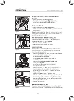
(3.8)


PERFORM CUTS CORRECTLY  

AND SAFELY

Always ensure that before each cut the mitre 

saw is mounted in a stable position.

If needed the mitre saw can be mounted on 

a wooden base or work bench or attached 

to a mitre saw stand as detailed in this 

Instruction Manual.

Long work pieces should be supported on the 

work supports provided or on appropriate 

additional work supports.
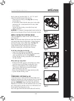
(3.9)


ADDITIONAL SAFETY ADVICE - 

CARRYING YOUR MITRE SAW

•  Although compact, this Mitre Saw is heavy. 

To reduce the risk of back injury,  

get competent help whenever you  

have to lift the saw.

•  To reduce the risk of back injury, hold the 

tool close to your body when lifting. Bending 

your knees so you can lift with your legs, not 

your back. Lift by using the handhold areas at 

each side of the machines base.

•  Never carry the Mitre Saw by the power 

cord. Carrying the Mitre Saw by the power 

cord could cause damage to the insulation 

or the wire connections resulting in electric 

shock or fire.

•  Before moving the Mitre Saw tighten the 

mitre and bevel locking screws and the 

sliding carriage locking screw to guard 

against sudden unexpected movement.

•  Lock the Cutting Head in its lowest position. 

Ensure that the Cutting Head Locking Pin is 

completely engaged in its socket.

WARNING: 

Do not use the blade guard as 

a ‘lifting point’. The power cord must be 

removed from the power supply before 

attempting to move the machine. 

•  Lock the Cutting Head in the down position 

using the Cutting Head Locking Pin. 

•  Loosen the Mitre Angle Locking Screw.  

Turn the table to either of its  

maximum settings. 

•  Lock the table in position using the 

Locking Screw. 

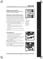
•  Use the two carry handle cut-outs 

machined into either side of the machine 

base, to transport the machine.

Содержание 046-0001

Страница 1: ...Originally written in UK English Date Published 01 08 2018 Original Instructions CMS F210...

Страница 2: ...m 1 4 Congratulations on your purchase of an Evolution Power Tools machine Please complete your product guarantee registration online as explained in the guarantee registration leaflet included with t...

Страница 3: ...onal support before cutting L 178 x W 20 x D 3mm 7 In MAXIMUM CUTTING ANGLES LEFT RIGHT Mitre 45 at 0 Bevel 45 at 45 Bevel 50 at 0 20 Bevel 45 at 21 45 Bevel Bevel 0 45 N A MITRE BEVEL MAX WIDTH OF CU...

Страница 4: ...amaged Contact Evolution Power Tools for replacement labels Note All or some of the following symbols may appear in the manual or on the product Manufacturing Date Code The manufacturing date code is...

Страница 5: ...1 POWER TOOL GENERAL SAFETY INSTRUCTIONS WARNING Read all safety warnings and instructions Failure to follow the warnings and instructions may result in electric shock fire and or serious injury Note...

Страница 6: ...e liquids or gases c Guard against electric shock Avoid body contact with earthed or grounded surfaces e g pipes radiators ranges refrigerators d Keep other persons away Do not let persons especially...

Страница 7: ...ould be used in a covered and dry area The ambient temperature should be between 15 C and 30 C The humidity level should be less than 60 3 5 MITRE SAW SPECIFIC SAFETY The following specific safety ins...

Страница 8: ...f the laser fails to operate it shall be repaired or replaced by the manufacturer or his authorised agent The saw blade shall only be replaced as detailed in this Instruction Manual Never attempt to r...

Страница 9: ...not throw the packaging away keep it safe throughout the guarantee period Dispose of the packaging in an environmentally responsible manner Recycle if possible Do not let children play with empty plas...

Страница 10: ...ALE 6 SLIDING FENCE LOCKING SCREW 7 REAR STABILISING ARM 8 DUST EXTRACTION PORT 9 CUTTING HEAD HANDLE 10 BLADE GUARD LOCKING LEVER 11 UPPER BLADE GUARD 12 SLIDING FENCE 13 LOWER BLADE GUARD 14 ROTARY...

Страница 11: ...nd properly supporting the workpiece Support the saw so the machine table is level and the saw does not rock Bolt or clamp the saw securely to its support stand or workbench 7 3 FOR PORTABLE USE Mount...

Страница 12: ...e necessary to allow the cutting head and blade to be lowered without them fouling any other parts of the machine To adjust the fence Loosen the thumbscrew Fig 5 Slide the upper section of the fence l...

Страница 13: ...ARNING Checks adjustments must only be conducted with the machine disconnected from the power supply BEVEL ANGLES 0 45 0 Bevel Stop Adjustment Ensure that the cutting head is in the locked down positi...

Страница 14: ...the cutting head and check for any blade contact with the machines base If the downward travel of the cutting head needs to be adjusted Loosen the locknut on the downward travel stop screw with a 10m...

Страница 15: ...uards 8 5 PREPARING TO MAKE A CUT WARNING Do not over reach Keep good footing and balance Stand to one side so that your face and body are out of line of a possible kickback Freehand cutting is a majo...

Страница 16: ...ial The cutting head is gently pushed down to cut through the workpiece Place the workpiece on the table and against the fence and secure with clamp s as appropriate Take hold of the cutting handle Tu...

Страница 17: ...t hand side only To tilt the cutting head to the left Loosen the bevel locking screw Fig 22 Tilt the cutting head to the required angle A protractor scale is provided as an aid to setting Fig 23 Tight...

Страница 18: ...consider using a remote workpiece support if thought necessary 8 11 INSTALLING OR REMOVING A BLADE Warning Only carry out this operation with the machine disconnected from the mains supply Note It is...

Страница 19: ...supplied hex key until the button locates fully into the shaft and locks the shaft Fig 26 Tighten the arbor screw using moderate force but do not overtighten Ensure the hex key is removed and the arb...

Страница 20: ...is lying flush and level within the table 6 1 MAINTENANCE Note Any maintenance must be carried out with the machine switched off and disconnected from the mains battery power supply Check that all sa...

Страница 21: ...Electronic Equipment WEEE Directive And is in conformity with the applicable requirements of the following documents EN61029 1 2009 A11 EN 61029 2 9 2012 A11 EN 55014 1 2017 EN55014 2 2015 EN61000 3...

Страница 22: ...22 www evolutionpowertools com Notes...

Страница 23: ...23 www evolutionpowertools com Notes...

Страница 24: ...er Tools SAS 61 Avenue Lafontaine 33560 Carbon Blanc Bordeaux T 33 0 5 57 30 61 89 UK Evolution Power Tools Ltd Venture One Longacre Close Holbrook Industrial Estate Sheffield S20 3FR T 44 0 114 251 1...

Отзывы: