


14
www.evolutionpowertools.com
45°
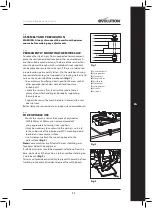
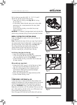
Bevel Stop Adjustment
• Loosen the bevel locking handle and tilt the cutting head
completely to the left until it rests against the 45°
stop.
• Use a set square (avoiding the TCT tips of the blade teeth),
check that the blade is at 45°
to the table.
• If the saw blade is not in exact alignment adjustment
is necessary.
• Return the cutting head to its upright position.
• Loosen the locknut on the 45°
bevel adjustment screw with
a 10mm spanner and 3mm Hex key (Not supplied).
• Use the Hex key to adjust the adjustment screw in or out
as required
(Fig. 11)
.
• Tilt the cutting head to the 45°
setting and recheck for
alignment with the set square.
• Repeat the above steps until the correct angular alignment
is achieved.
• Tighten the adjustment screw locknut securely once
alignment is achieved.
CUTTING HEAD TRAVEL
Cutting Head Downward Travel Adjustment
To prevent the blade from contacting any part of the machines
metal base the downward travel of the cutting head can be
adjusted. Lower the cutting head and check for any blade
contact with the machines base.
If the downward travel of the cutting head needs to be adjusted:
• Loosen the locknut on the downward travel stop screw with
a 10mm spanner (Not supplied)
(Fig. 12A)
.
• Turn the adjusting screw
(Fig. 12B)
out (counter-clockwise)
with a 5mm Hex key (Not supplied) to decrease the
downwards travel of the cutting head.
• Turn the adjusting screw in (clockwise) to increase the
downwards travel of the cutting head.
• Tighten the adjustment screw locknut when satisfactory
downward travel of the cutting head is achieved.
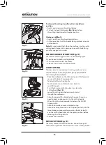
FENCE ALIGNMENT
The fence must be aligned at 90°
(square) to a correctly
installed blade. The rotary table must be set at 0° mitre angle.
Note:
The fence is fastened to the machines base with two
socket head Hex screws positioned at either end of the fence
in elongated slots
(Fig. 13)
.
• Ensure that the cutting head is in the locked down position
with the latching pin fully engaged in its socket
(Fig. 16)
.
• Place a set square on the table with one short edge
against the fence and the other short edge against
the blade (avoiding the TCT tips of the blade teeth)
(Fig. 14)
.
• Repeat on both sides of the blade.
Fig. 11
Fig. 12A + 12B
Fig. 13
Fig. 14
A
B