8
www.evolutionpowertools.com
DEPLOYING THE LEGS PRIOR TO ASSEMBLY
Note:
It is much easier to set up or knock down the stand without
a saw being attached.
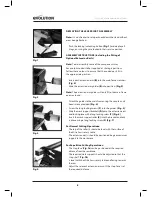
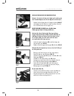
• Push the locking/unlocking button
(Fig. 1)
and deploy all
4 legs, ensuring they are locked in their service position.
ASSEMBLY INSTRUCTIONS (Including the fitting of
Optional Extension Rails)
Note:
To aid assembly some of the components may
have colour coded stickers applied at strategic positions.
Follow these colours to ensure that the coded parts fit in
the appropriate position.
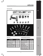
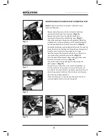
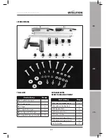
• Insert each extension arm
(B)
into the mainframe crossbars.
(Fig. 2)
• Slide the extension arm guides
(E)
into position.
(Fig. 3)
Note:
The extension arm guides will only fit to the main frame
one way round.
• Attach the guides to the main frame using the countersunk
head screws provided.
(Fig. 4)
• Screw the long locking screws
(F)
into the guides.
(Fig. 5)
• Slide the work support brackets
(D)
onto the extension arms
and lock in place with a long locking screw
(F)
.
(Fig. 6)
• Insert the work support roller
(C)
into the bracket and lock
in place using a long locking screw.
(F) (Fig. 7)
For Normal Cutting Operations:
• The top of the roller(s) should be level with the surface of
the Mitre Saws rotary table.
• The extension arm(s) should be positioned be give maximum
support to the workpiece.
For Repetitive Cutting Operations:
• The ‘stop face’ (
Fig. 7a
) can be positioned at the required
distance from the saw blade.
• The required work support should be adjusted so that the
‘stop shelf’ (
Fig. 7b
)
is level with the Mitre Saws rotary table and facing towards
the saw.
• Adjust the relevant extension arm until the ‘stop face’ is at
the required distance.
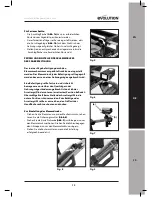
Fig. 1
Fig. 2
Fig. 3
Fig. 4
Содержание 005-0001
Страница 2: ......
Страница 3: ...EN DE FR ENGLISH Original Instructions ...
Страница 12: ......
Страница 13: ...EN DE FR DEUTSCH Übersetzung ursprünglichen Anweisungen ...
Страница 22: ......
Страница 23: ...EN DE FR FRANÇAIS Traduction des instructions d origine ...


