background image

Discover Evolution Power Tools

Visit: 

www.evolutionpowertools.com

 or download 

the QR Reader App on your smart phone and scan 
the QR code (Right).

UK

Evolution Power Tools Ltd
Venture One
Longacre Close
Holbrook Industrial Estate
Sheffield
S20 3FR

+44 (0)114 251 1022

US

Evolution Power Tools LLC
8363 Research Drive
Davenport
Iowa
52806

+1 866-EVO-TOOL

EU

Evolution Power Tools SAS
61 Avenue Lafontaine
33560
Carbon-Blanc
Bordeaux

+ 33 (0)5 57 30 61 89

V1.11

Содержание 005-0001

Страница 1: ...EN DE FR MITRE SAW STAND 005 0001 Original Instructions Date Published 10 12 2015 Original written in UK English ...

Страница 2: ......

Страница 3: ...EN DE FR ENGLISH Original Instructions ...

Страница 4: ...ons 06 Stand Specific Safety Instructions 06 GETTING STARTED 06 Stand Features 06 Parts Supplied 07 Deploying The Legs Prior To Assembly 08 Assembly Instructions 08 Checking And Adjusting The Saw Mounting Bracket Clamping Pressure 09 Mounting Evolution Mitre Saw To The Mitre Stand 10 Mounting Unusual Or Uncommon Mitre Saws 11 This manual is originally written in UK English ...

Страница 5: ...will within the guarantee period and from the original date of purchase repair or replace any goods found to be defective in materials or workmanship This guarantee is void if the tool being returned has been used beyond the recommendations in the Instruction Manual or if the machine has been damaged by accident neglect or improper service This guarantee does not apply to machines and or component...

Страница 6: ...ication Do not overreach Keep proper footing and balance at all times STAND SPECIFIC SAFETY INSTRUCTIONS For maximum stability use the mitre stand only on a flat level surface Be careful when raising or lowering the stand to prevent trapped fingers or hands Ensure that the snap buttons on each leg are in the locked position This will ensure that the stand remains rigid during cutting operations Do...

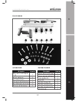
Страница 7: ...kets 2 B Extensions Arms 2 C Work Supports 2 D Work Support Brackets 2 E Extension Arm Guides 2 F Long Locking Screws 6 ASSORTED FIXINGS SUPPLIED Description Quantity M6 Coach Bolts Long 4 M6 Coach Bolts Short 4 M6 Wing Nuts 4 M6 Plain Nuts 4 M6 Spring Washers 4 M6 Plain Washers small 4 M6 Plain Washers large 4 Countersunk Head Screws 4 ...

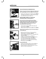
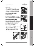
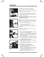
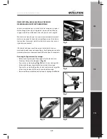
Страница 8: ...d Attach the guides to the main frame using the countersunk head screws provided Fig 4 Screw the long locking screws F into the guides Fig 5 Slide the work support brackets D onto the extension arms and lock in place with a long locking screw F Fig 6 Insert the work support roller C into the bracket and lock in place using a long locking screw F Fig 7 For Normal Cutting Operations The top of the r...

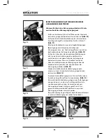
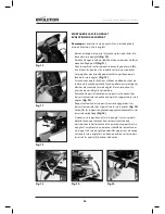
Страница 9: ...a bracket should be firm and exhibit no signs movement Excessive force to deploy the locking lever to the down position should be avoided Gently pressing the lever downwards with the palm of a hand should be all the force needed to operate the locking lever To adjust the clamping pressure Turn the clamp upside down to reveal the mechanism Loosen the locking nut Fig 8 Turn the adjustment screw Fig ...

Страница 10: ...f the machine that they interfere with any other parts of the Mitre Saw Only tighten finger tight at this stage Hook the front of the brackets over the front of the mitre saw stands main frame tubular crossbar Fig 13 Push the back of the brackets down to engage them onto the mitre saw stands crossbars Fig 14 Lock the brackets into place by gently depressing the locking levers Fig 15 If necessary r...

Страница 11: ...ular piece of plywood or worktop should be sourced which will fit the footprint and mounting hole configuration of your saw The adaptor plate should be drilled and bolted to the saw mounting brackets using appropriate bolts or fixings etc The adaptor plate can then be attached to the mitre saw stand and the mitre saw positioned upon the adaptor plate For stability during use care should be taken t...

Страница 12: ......

Страница 13: ...EN DE FR DEUTSCH Übersetzung ursprünglichen Anweisungen ...

Страница 14: ...shinweise Für Den Ständer 16 EINSTIEG 16 Eigenschaften Des Ständers 16 Lieferumfang 17 Ausklappen Der Füsse Vor Der Montage 18 Montageanweisungen 18 Prüfen Und Einstellen Des Klemmdrucks Der Sägebefestigung 19 Befestgung Einer Evolution Gehrungssäge Am Gehrungssägeständer 20 Befestigen Ungewöhnlicher Oder Unüblicher Gehrungssägen 21 Dieses Handbuch ist ursprünglich in Großbritannien Englisch gesch...

Страница 15: ...it und aus dem ursprünglichen Kaufdatum reparieren oder ersetzen Ware mangelhaft befunden werden Material oder Herstellungsfehler Diese Garantie ist ungültig wenn das Werkzeug zurückgegeben hat über die Empfehlungen in der Bedienungsanleitung oder wenn die Maschine durch einen Unfall Vernachlässigung oder unsachgemäße Wartung beschädigt worden Diese Garantie gilt nicht für Maschinen und oder Kompo...

Страница 16: ...n Sorgen Sie für einen festen Stand Achten Sie auf jederzeit sicheren Stand und gutes Gleichgewicht SPEZIFISCHE SICHERHEITSHINWEISE FÜR DEN STÄNDER Maximale Stabilität erhalten Sie nur wenn Sie den Gehrungssägeständer auf einer ebenen waagrechten Fläche verwenden Seien Sie beim Erhöhen oder Absenken des Ständers vorsichtig um die Finger oder Hände nicht einzuklemmen Stellen Sie sicher dass sich di...

Страница 17: ...legerarme 2 C Träger 2 D Trägerhalterungen 2 E Auslegerarmführungen 2 F Lange Befestigungsschrauben 6 MITGELIEFERTES BEFESTIGUNGSSORTIMENT Beschreibung Menge M6 Schlossschrauben lang 4 M6 Schlossschrauben kurz 4 M6 Flügelmuttern 4 M6 Einfache Muttern 4 M6 Federscheiben 4 M6 Einfache Scheiben klein 4 M6 Einfache Scheiben groß 4 Senkschrauben 4 ...

Страница 18: ...Auslegerarm B in die Querträger des Hauptrahmens ein Abb 2 Schieben Sie die Auslegerarmführungen E in Position Abb 3 Hinweis Die Auslegerarme passen nur in einer Stellung in den Hauptrahmen Befestigen Sie die Führungen mit den mitgelieferten Senkschrauben am Hauptrahmen Abb 4 Schrauben Sie die langen Befestigungsschrauben F in die Führungen Abb 5 Schieben Sie die Trägerhalterungen D auf die Ausleg...

Страница 19: ...an einer Gehrungssäge angebracht wird Eine Befestigung sollte fest sein und sich nicht bewegen wenn sie über den Querträgern des Gehrungssägeständers angebracht ist und sich der Arretiergriff in der unteren arretierten Position befindet Übermäßige Kraft beim Stellen des Arretiergriffs in die untere Position ist zu vermeiden Zum Betätigen des Arretiergriffs sollte es ausreichen den Griff mit der Ha...

Страница 20: ...er Maschine vorstehen dass sie andere Teilen der Gehrungssäge behindern In dieser Phase nur handfest anziehen Haken Sie die Vorderseite der Befestigungen über die Vorderseite des Querrohrs des Hauptrahmens des Gehrungssägeständers Abb 13 Drücken Sie die Rückseite der Befestigungen nach unten um sie am Querrohr des Gehrungssägeständers einzurasten Abb 14 Arretieren Sie die Befestigungen an Ort und ...

Страница 21: ... nach einem quadratischen oder rechteckigen Stück Sperrholzplatte oder Arbeitsplatte das zur Aufstandsfläche und Befestigungsbohrungskonfiguration Ihrer Säge passt Die Adapterplatte sollte gebohrt und mit geeigneten Schrauben oder Befestigungen etc an die Sägebefestigungen geschraubt werden Die Adapterplatte kann dann an den Gehrungssägeständer angebracht werden und die Gehrungssäge kann auf der A...

Страница 22: ......

Страница 23: ...EN DE FR FRANÇAIS Traduction des instructions d origine ...

Страница 24: ...nes De Securite Specifiques Au Support 26 MISE EN ROUTE 26 Caracteristiques Du Support 26 Pieces Fournies 27 Deploiement Des Pieds Avant Assemblage 28 Instructions D assemblage 28 Verification Et Reglage De La Pression De Serrage Du Support De Montage 29 Montage De La Scie A Onglet Evolution Sur Le Support 30 Montage De Scies A Onglets Speciales 31 Ce manuel est rédigé en anglais britannique ...

Страница 25: ...ns la période de garantie et à partir de la date d achat originale réparer ou remplacer tout produit reconnu défectueux dans les matériaux ou de fabrication Cette garantie est nulle si l outil retournées a été utilisé au delà des recommandations contenues dans le manuel d instructions ou si l appareil a été endommagé par accident négligence ou une mauvaise utilisation Cette garantie ne s applique ...

Страница 26: ...igué si vous avez consommé des drogues ou de l alcool ou si vous êtes sous les effets d un médicament Ne vous penchez pas trop Gardez une bonne assise et un bon équilibre à tout moment CONSIGNES DE SECURITE SPECIFIQUES AU SUPPORT Pour une stabilité maximum n utilisez le support que sur une surface plate et horizontale Faites attention de ne pas vous coincer les doigts lorsque vous montez ou baisse...

Страница 27: ...xtension 2 C Guides de travail 2 D Supports de guides de travail 2 E Guides de bras d extension 2 F Ecrous de fixation longs 6 FIXATIONS FOURNIES Description Quantite Boulons de carrosserie M6 longs 4 BoulonsdecarrosserieM6 courts 4 Ecrous papillons M6 4 Ecrous M6 4 Rondelles élastiques M6 4 Rondelles plates M6 petites 4 Rondelles plates M6 grandes 4 Vis à tête fraisée 4 ...

Страница 28: ...des au cadre principal en utilisant les vis tête fraisée qui vous ont été fournies Fig 4 Vissez les écrous de fixation longs F dans les guides Fig 5 Faites glisser les supports de guides de travail D sur les bras d extension et fixez les en place avec un écrou de fixation longs F Fig 6 Insérez le galet de support de travail C dans le support et fixez le en place avec un écrou de fixation longs F F...

Страница 29: ...ntrer aucun signe de mouvement Il faut éviter d exercer une force excessive lors de la mise en position basse du levier de verrouillage Une légère pression de la paume de la main est normalement suffisante pour le manipuler Pour régler la pression de serrage Retournez la pince pour faire apparaître le mécanisme Dévissez l écrou autobloquant Fig 8 Tournez la vis de réglage Fig 9 dans le sens des ai...

Страница 30: ...ner d autres éléments de la scie à onglet Ne serrez qu avec la pression de vos doigts à cette étape Accrochez la partie frontale des supports sur le devant des barres transversales du cadre principal du support de la scie à onglet Fig 13 Repoussez le dos des supports pour les engager dans les barres transversales des supports de la scie à onglet Fig 14 Verrouillez les supports en place en appuyant...

Страница 31: ...r un morceau de contreplaqué ou de plan de travail qui corresponde à l empreinte et à la configuration des trous de montage de votre scie Lacalederéglagedoitêtrepercéeetboulonnéesurlessupports de montage de la scie avec les boulons et fixations adaptés La cale de réglage peut dès lors être fixée au support de la scie à onglet et la scie à onglet positionnée sur la cale de réglage Pour une bonne st...

Страница 32: ... the QR code Right UK Evolution Power Tools Ltd Venture One Longacre Close Holbrook Industrial Estate Sheffield S20 3FR 44 0 114 251 1022 US Evolution Power Tools LLC 8363 Research Drive Davenport Iowa 52806 1 866 EVO TOOL EU Evolution Power Tools SAS 61 Avenue Lafontaine 33560 Carbon Blanc Bordeaux 33 0 5 57 30 61 89 V1 11 ...

Отзывы: