background image

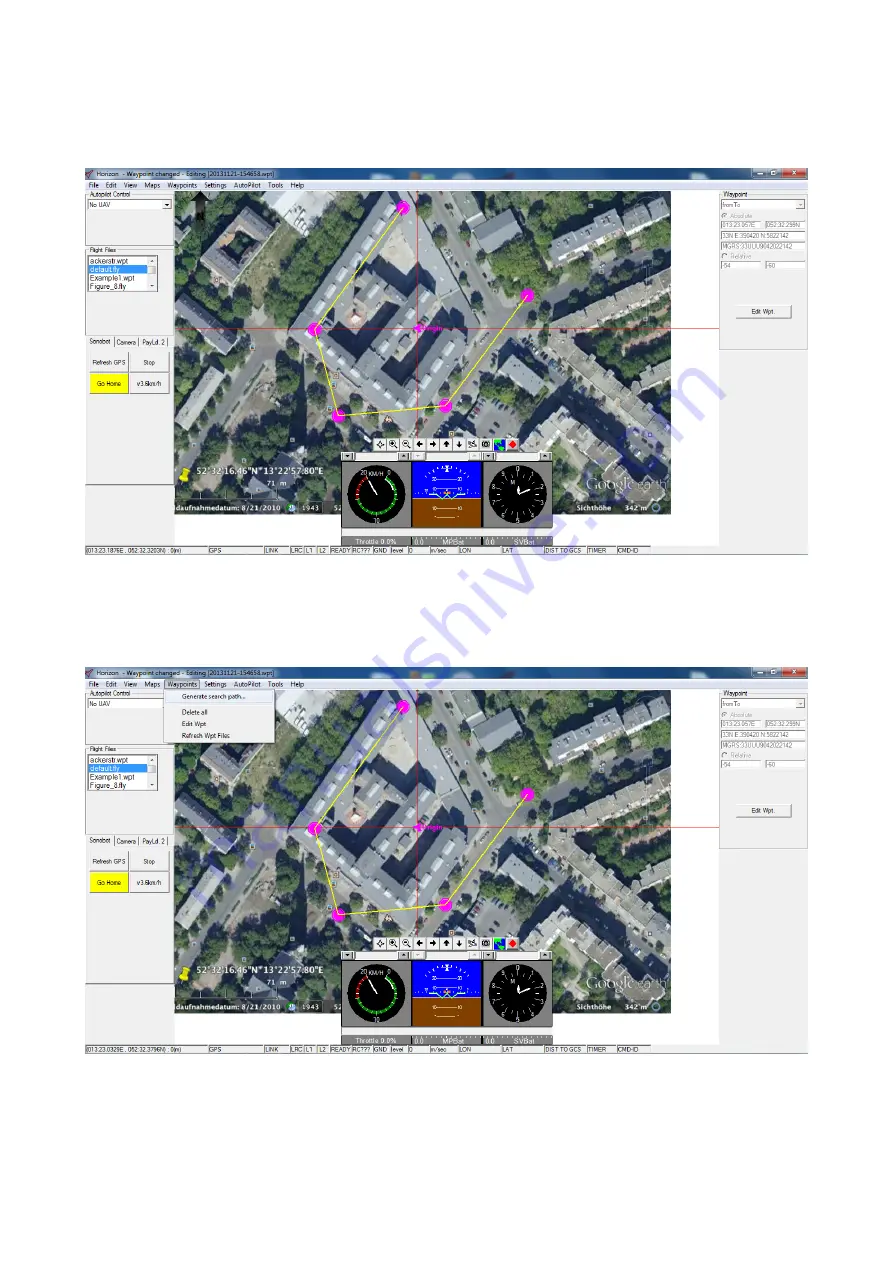
• Make an open perimeter around the operating area, placing at least three waypoints, as described above. Remember

to use the

fromto

command from the

Append Waypoint

menu when placing new waypoints to create a perimeter.

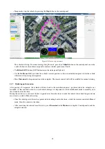
The image below provides an example of the perimeter, placed around an area on the map.

Figure 38: Horizon: creating a perimeter around the area

• Create a survey grid within the boundary, placed around the operating area on the previous step:

go to

Menu

Waypints

Generate Search Path...

to automatically create a grid within the perimeter.

Figure 39: Horizon: create a grid

33

Содержание Sonobot

Страница 1: ...EvoLogics GmbH Ackerstr 76 13355 Berlin Germany Tel 49 30 4679 862 0 Fax 49 30 4679 862 01 Email support evologics de EvoLogics Sonobot Autonomous Surface Vehicle User Guide Version 1 0 March 2018 ...

Страница 2: ... The publication may not be modified in any way Any copy of the publication or portion thereof must include all original copyright trademark and other proprietary notices and this permission statement and EvoLogics reserves the right to revoke this authorization at any time and any such use shall be discontinued imme diately upon written notice from EvoLogics Disclaimer Information in this publica...

Страница 3: ... 2 1 Configure the map 25 4 2 2 Create the mission plan 31 4 2 3 Transmit the waypoints file 38 4 2 4 Connect to autopilot 41 4 2 5 Start the mission 42 4 2 6 During the mission 44 4 2 7 Finishing up the mission 45 4 3 Sonobot 2 software 46 4 3 1 General 46 4 3 2 Status Tab 47 4 3 3 Echosounder Tab 48 4 3 4 Echosounder Display Tab 50 4 3 5 Advanced Tab 52 4 4 DeepView software 53 4 4 1 Overview 53...

Страница 4: ... descriptions and instructions on setting up the Sonobot hardware Section 4 provides an overview of the software supplied with the system including autopilot control software vehicle access software echosounder control software and side scan sonar software Details on using the software for planning configuring and executing the mission are provided Section 5 contains instructions on launching the ...

Страница 5: ...atches that are both secure and fast to unlock Section 3 provides step by step instructions on assembling the Sonobot The on board equipment of the vehicle depending on the configuration includes a differential GPS system a single beam echo sounder a side scan sonar a wireless communication system a radio control system an autopilot and the on board PC The shore equipment comprises a wireless LAN ...

Страница 6: ... unlock You do not need any tools to assemble the vehicle before the mission Follow the steps below to assemble the Sonobot Unpack the floater stands supplied with the vehicle and place them on a flat surface see Fig 2 below The stands will protect the floaters during assembly and on shore testing Take the floaters out of the transport case and place them on the stands connecting cables facing inw...

Страница 7: ...e mount spikes of the floaters Make sure the crossbars are perpendicular to the floaters Figure 3 Sonobot assembly To tighten a latch turn it until you feel it lock see the C marking on the latch Fig 4 Figure 4 Fastening the latches Fasten all 4 latches holding the floaters and the crossbars together The crossbars and the floaters are now locked 6 ...

Страница 8: ... Mind the front and place the main body onto the crossbars Fasten the screws under the crossbars to lock the main body in place The Sonobot is now assembled Figure 5 Sonobot assembly 7 ...

Страница 9: ...en the connector screws Figure 6 Sonobot assembly 1 Connectors 2 Main body latches 3 WLAN antenna 4 On Off switch Close the unused sockets on the main body with the attached screw caps Make sure you tighten the waterproof caps to avoid leakage Make sure the eccentric latches 2 in Fig 6 on the main body are fastened tight enough to avoid leakage into the main body of the vehicle 8 ...

Страница 10: ...antenna Connect the GPS connecting cable to the GPS antenna Figure 8 The GPS antenna Put the antenna into the corresponding slot on the main body fasten it by turning clockwise until you feel it lock Push the loose GPS cable into the main body and fasten the cable holder Raise the WLAN antenna 3 in Fig 6 on the main body 9 ...

Страница 11: ...f switch 4 in Fig 6 180 degrees The On Off indicator on the switch will start blinking The side lights will light up red and green see image below Figure 9 Turning on the Sonobot To turn off the Sonobot turn the switch into the Off position 10 ...

Страница 12: ...with the notebook for details Mind the following considerations when setting up the field PC before the mission Make sure the field PC is fully charged or make arrangements for an external power supply The field PC connects to the WLAN box with a 5 m Ethernet cable supplied by EvoLogics Mind the cable length and the planned WLAN station position when choosing a spot for the field PC Although the f...

Страница 13: ...e The antenna is directional make sure the antenna s front 1 is facing the operating area so that the area is covered by the antenna s range When choosing a spot for the antenna make sure there will be no obstacles between the station and the Sonobot s operating area Installing the antenna at an elevated spot will benefit the signal reception quality The stable tripod provided with the antenna is ...

Страница 14: ...controls and connectors The On Off switch 1 turns the WLAN box on off Press the Battery level button 2 to see the battery level on the light indicator to the right The charging 3 Ethernet 4 and the antenna 5 connectors are protected with screw caps on the back of the WLAN box 13 ...

Страница 15: ... spread its legs and set it on even ground Screw the antenna holder onto the tripod as shown below Figure 13 WLAN station antenna holder Put the antenna onto the holder With two wing screws supplied attach it as shown below Figure 14 WLAN station assemble the antenna 14 ...

Страница 16: ...it is stable enough to withstand eventual wind gusts etc Connect the antenna to the WLAN box with the cable supplied Figure 15 WLAN station connect the antenna Connect the WLAN box to the Field PC with the 5 m Ethernet cable supplied Open the WLAN box and turn on the station with the On Off switch Make sure you close the box after powering up the station 15 ...

Страница 17: ...it Therefore the vehicle will move at chosen constant speed without the need to hold the control stick After you have set the constant operating speed with the Throttle stick mind the operating conditions such as water currents waves wind you can manually speed up down by moving the steering stick back and forth if needed Release the left stick to go back to the chosen operating speed The throttle...

Страница 18: ...original chargers supplied with the system Charging batteries should never be left unattended due to a risk of fire or explosion Do not store fully charged batteries over long periods of time several weeks The batteries are best to store at half charge It is not necessary to take out the batteries for charging three 3 5 A battery chargers are supplied with the Sonobot to charge the battery packs w...

Страница 19: ...cting cables from the main body Connect the propulsion battery chargers 8 pin connectors to the cables Plug the chargers into a power source The charging indicators will light green once charging is complete Refer to the manufacturer s guide provided with the chargers if necessary Unplug the chargers from the power source and disconnect them from the floaters Connect the floaters back to the main ...

Страница 20: ...ware Please refer to the manufacturer s guide for detailed information 4 1 1 Connecting to the vehicle To connect to the Sonobot s on board PC with the Radmin Viewer Launch the Radmin Viewer on the field PC use the desktop shortcut or the Start Menu shortcut In the main window choose Sonobot from the list of the available connections Figure 19 Radmin Viewer select the Sonobot The security window w...

Страница 21: ...connection is established in the Radmin Viewer window you will see the on board PC s screen with the Sonobot 2 software open read more about the Sonobot 2 in section 4 3 Figure 21 Radmin Viewer Sonobot screen 20 ...

Страница 22: ...oard PC over Radmin Viewer If you minimize or close the Sonobot 2 window you will see the on board PC s desktop Figure 22 Radmin Viewer on board PC desktop The desktop contains shortcuts to all software needed for Sonobot operation 21 ...

Страница 23: ...C Don t close these windows the services are needed for correct vehicle operation The serial2 py script displays the GPS output GPGGA sentences and service information Figure 23 Radmin Viewer serial2 service program If you have accidentally closed any service program relaunch it with the corresponding desktop shortcut 22 ...

Страница 24: ...sponding button in the toolbar The file transfer window will open Figure 24 Radmin Viewer on board PC desktop In the right panel browse for files on the on board PC of the vehicle In the left panel browse for the destination folder on the field PC Figure 25 Radmin Viewer on board PC desktop To transfer the file simply drag and drop it from the right panel to the left Please refer to the Radmin Vie...

Страница 25: ... description and instructions on using it to plan and conduct autopilot missions Please mind that the autopilot and the software were originally intended for flying model aircraft so the document contains some details that are not relevant for a surface vehicle Sections below will provide you a quick step guide on planning and executing a Sonobot mission including Sonobot specific details on confi...

Страница 26: ...raphic location in Horizon you will need an image of the area and geographical coordinates of two points on that image Proceed as described below Open the Horizon software on the field PC use the desktop shortcut Open the Map Selector plug in go to Menu Maps Show Map Selector Figure 27 Horizon opening Map Selector The main window of the plug in will display a list of available maps Figure 28 Horiz...

Страница 27: ...r in the Map Selector s map list To be displayed at the correct position the map must be georeferenced To enter the coordinates of the map manually double click on the map you just created in the map list to open the Select Map Coordinates dialog You must know the geographical coordinates of two points on the map to set up its location in Horizon refer to the manufacturer s guide for more options ...

Страница 28: ... are using two tie points to reference the map you must first place the tie points on it click 1 or 2 in the left panel of the dialog or right click on the map and select Place Tie Point 1 or Place Tie Point 2 from the drop down menu Figure 31 Horizon place Tie Points You can zoom in out scroll and drag the map view to place the points If needed use click and drag to move the tie point you placed ...

Страница 29: ... After the coordinates of reference points are entered press Ok to accept them Figure 32 Horizon accept map coordinates Next the origin of the map must be set up 28 ...

Страница 30: ...the map in the main Map Selector window select the map from the list and press the Select Autopilot Origin button see Fig 27 The Select Autopilot Origin dialog will open Figure 33 Horizon Select Autopilot Origin dialog 29 ...

Страница 31: ... Check the map in the map list of the Map Selector This map will be active the next time the Horizon starts Press Save in the Map Selector plug in The map is now ready to use for Sonobot mission planing Close the Horizon software Do not proceed with mission planning after setting up the operating area map you must close the program and restart it to continue Refer to the Horizon manufacturer s gui...

Страница 32: ... a waypoint file follow the steps below Open the Horizon software on the field PC use the desktop shortcut Go to Menu File New Waypoint File to create a new waypoint file Figure 35 Horizon create new waypoints file The map of the area you created and activated at the previous step see 4 2 1 is displayed in the Map area Figure 36 Horizon editing new waypoints file 31 ...

Страница 33: ...and the vehicle in this case will not travel along a straight path compromising the measurements Longitude and Latitude are absolute coordinates do not use the relative coordinates the command above in the Append Waypoint menu as the vehicle will then travel the programmed path regardless of the launch location This is unsuitable for most Sonobot applications Figure 37 Horizon adding a new waypoin...

Страница 34: ...ints to create a perimeter The image below provides an example of the perimeter placed around an area on the map Figure 38 Horizon creating a perimeter around the area Create a survey grid within the boundary placed around the operating area on the previous step go to Menu Waypints Generate Search Path to automatically create a grid within the perimeter Figure 39 Horizon create a grid 33 ...

Страница 35: ...defines the space between two generated waypoints within the grid We recommend setting the waypoint spacing at 200 m Altitude ASP m setting is irrelevant for Sonobot missions set it to 1 m The Track heading setting defines the angle of the grid lines Leave the Calculate waypoints from camera parameters and Use custom waypoint commands check boxes unchecked Figure 40 Horizon generate a grid 34 ...

Страница 36: ...s file Enter the file name into the corresponding field Choose Sonobot std fly from the list of available Wission Types and press Save The waypoint file will be saved to the default saving location C Program Files Horizon3 4 fly We recommend to save the file to the default folder Figure 41 Horizon generate a grid 35 ...

Страница 37: ... The generated grid will be displayed Make corrections if needed Go to Menu File Save Waypoint File to save the final waypoint configuration for the autopilot mission Figure 42 Horizon save a grid 36 ...

Страница 38: ... overwrite it or enter the new filename Press Save Figure 43 Horizon save the waypoint file The waypoint file for the next autopilot mission is now ready Go to Menu File Close Waypoint File to finish editing the waypoint file 37 ...

Страница 39: ...g at the mission site After you assemble and turn on the vehicle and the WLAN station as described in section 3 turn on the field PC and connect to Sonobot see section 4 1 Follow the steps below to transmit the waypoints file to the autopilot From the Autopilot control drop down list in the left control panel select UAV 01 Do NOT press Connect at this step Figure 44 Horizon select the vehicle 38 ...

Страница 40: ...nt file you want to transmit to the autopilot for the mission Press the Transmit Waypoints button to the right of the list Figure 45 Horizon select the waypoint file The Transmit Waypoints dialog will appear Press Transmit Figure 46 Horizon transmit the waypoint file 39 ...

Страница 41: ...ransmission progress Press Close when transmission is complete Figure 47 Horizon transmit the waypoint file The waypoints file for the mission is now loaded into the autopilot The autopilot is programmed for the next mission 40 ...

Страница 42: ...nual operation mode Please mind that the remote control must also stay on when the autopilot is active To avoid unexpected maneuvers of the vehicle the remote control unit should be turned off last after the vehicle is completely powered off Follow the steps below to connect to the autopilot Open the Horizon software on the field PC From the Autopilot control drop down list in the left control pan...

Страница 43: ...ontrol is turned on and is in Manual mode Follow the steps below to launch the autopilot and enable manual and automatic steering In the Autopilot control panel click the Arm button The autopilot will get ready for launch Make sure the remote control is turned on and is in Manual mode Figure 49 Horizon confirm connection Figure 50 Horizon arm the autopilot 42 ...

Страница 44: ...gure 51 Horizon launch the autopilot Now the autopilot and the remote control are initialized The vehicle s propulsion system is now controlled by the remote control You can perform the necessary on shore and near shore checks as described in secton 5 43 ...

Страница 45: ...ow moving along the programmed route 4 2 6 During the mission During the mission monitor the vehicle on the Horizon map as it passes the waypoint grid During the mission you can perform the following actions in Horizon software Speed up and down with the corresponding buttons in the instruments panel Fly to selected waypoint The vehicle will ride directly to the selected waypoint and continue the ...

Страница 46: ... control will still be available for manual steering 4 2 7 Finishing up the mission After passing all waypoints the vehicle will drive back to the initialization point position where the autopilot was launched As this occurred on land to avoid vehicle damage it is important to switch into Manual mode to manually steer the vehicle back to the shore During the mission you can move the last waypoint ...

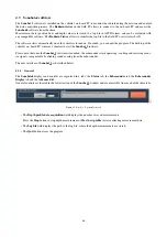
Страница 47: ...nobot 2 software Please note that once the Sonobot 2 software is launched the echosounder starts operating sending and receiving acous tic signals recognizable by clicking sound coming from the echosounder The user interface of Sonobot 2 is described below 4 3 1 General The Sonobot 2 displays and controls are organized in 4 tabs the Status tab the Echosounder tab the Echosounder Display tab and th...

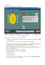
Страница 48: ...any battery pack drops down to 13 V the mission must be stopped for battery recharge The GPS string field displays the ASCII output of the GPS receiver as a set of comma delimited values Please refer to the supplied manufacturer s information for a detailed description of the GPS receiver output This field is for diagnostic purposes only The last measured depth value is displayed below the GPS str...

Страница 49: ...S antenna extension in m Set this value to 0 2 m if you are using the extension supplied by EvoLogics The Water Level m field is the elevation height above mean sea level of the operating area in m 4 3 3 Echosounder Tab The Echosounder tab of the Sonobot 2 software is pictured below Figure 56 Sonobot 2 Echosounder tab The Echosounder tab allows to configure the vehicle s echo sounder settings Afte...

Страница 50: ...d Period ms is set to 500 ms 2 measurements per second If for a certain area less data samples are required for example to reduce the saved data volume you can increase the period in ms by editing the Period ms field The Threshold field 0 1 defines the detection threshold for received echo signals The default 0 3 setting means that the threshold is set at 0 3 30 of the maximum received signal ampl...

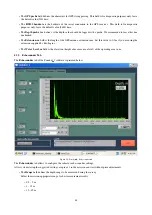
Страница 51: ...veys in unfamiliar areas The left sub plot displays a received signal that corresponds to the last measurement As seen in the example above the first echo signal is a high amplitude pulse with steep rising and falling edges This signal corresponds to an accurate depth measurement The main frame on the right displays the time depth plot of the measurement data Provided the propulsion was steady and...

Страница 52: ...e shore Above 6 m the lake bottom is more solid resulting in higher density echo signals Below 6 m deep 1 the lake bottom is covered in sediments so signal density is lower Empty sections with missing data are caused by the vehicle s fast turnarounds during the mission Here air bubbles under the echosounder obstruct depth measurements 1 as well as at 2 where the chosen propulsion speed was too hig...

Страница 53: ...ight above water S in m and the height of the antenna s extension V in m The last value repeats the Extension m value from the Status tab The COM to DeepView and GPS COM define the input output serial ports for communication to the DeepView software and to the GPS receiver respectively The GPGGA out field displays the full output of the GPS receiver the ASCII sentences The Depth COM status and GPS...

Страница 54: ...4 1 Overview The main window of Deep View SE is pictured below Figure 60 DeepView SE 4 4 2 Recording measurement data Before you begin Make sure the Serial2 py service script is running on the on board PC If you accidentally closed it use the desktop shortcut to relaunch it Make sure the Sonobot 2 software is running on the on board PC Relaunch it with the desktop shortcut if needed In Deep View m...

Страница 55: ...sure distances on the map with the Measure distance tool Export the data to Google Earch with the Google Earth tool internet connection is required Click on the data to display the vehicle s route 3D visualisation of the survey area In the Map View select the area to be visualised with the Select area tool Right click on the selected area and choose 3D from the pop out menu A 3D image will appear ...

Страница 56: ...rd PC once its desktop appears in the Radmin Viewer window and the monitoring software Sonobot 2 launches See section 4 1 for details In the Status tab of the Sonobot 2 software check battery voltages see section 4 3 for details Remember that voltage under 13 V is not acceptable for vehicle operation Proceed only if the batteries are charged enough Make sure the Auto Range OFF box is checked in th...

Страница 57: ...the Echosounder tab In small increments adjust the sound velocity value in the corresponding field and monitor the depth measured by the echosounder Repeat until the echosounder s depth estimation matches with the manually measured depth value Automated procedure At Sonobot s location use a c profiler to measure the sound velocity in water Refer to manufacturer s guide for detailed instructions Go...

Страница 58: ...able for missions in most inland water bodies or sea harbors Do not operate the vehicle if the wind is stronger than 3 Bft and the waves are higher than 0 3 m During the mission avoid areas covered in debris or vegetation Mind the risk of floating debris clogging the jet thrusters have a boat of proper size on hand to recover the vehicle in case of such emergency 5 4 Battery monitoring Battery vol...

Отзывы: