Assembly and Maintenance
PPC-1561
- 19 -
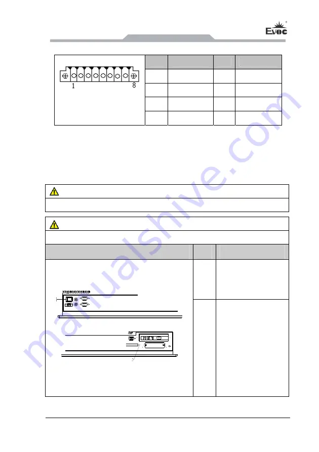
5.3.7 GPIO Port
Pin
Signal Name
Pin
Signal Name
1 GPIO1 2 GPIO2
3 GPIO3 4 GPIO4
5 GPIO5 6 GPIO6
GPIO1
(pitch: 3.81mm)
7 GPIO7 8 GPIO8
Note: By the factory default, pin 1, 2, 3 and 4 are for input while pin 5, 6, 7 and 8 are
for output. The factory default state is high level and the voltage range for
input/output signal is 0-5V.
5.4 Operation Control
Warning
The On/Off button signal will not disconnect PC power supply!
Caution
When the PC executes hardware reset, data may be lost.
Control Button
Item
Description
①
The On/Off switch
button used to power
on the PC.
②
Reset button
A pointed object or a
clip can be used to
press reset button, and
the signal will trigger
hardware reset. Then
the PC will be rebooted
(cold boot).
Содержание PPC-1561
Страница 13: ...产品安装说明 PPC 1561 7 3 2 产品外形尺寸图 备注 此机型分带 PCI 扩展与不带 PCI 扩展 其外形区别仅在于侧面板和扩 展盖有无通风孔 带扩展时有 不带扩展时无 单位 mm ...
Страница 14: ...产品安装说明 8 PPC 1561 3 3 安装尺寸图 3 3 1 产品安装尺寸图 单位 mm ...
Страница 15: ...产品安装说明 PPC 1561 9 3 3 2 推荐开孔尺寸图 单位 mm ...
Страница 17: ...设备连接 PPC 1561 11 4 3 将设备连接到电源 将设备连接到电源的步骤 将电源线连接到插口1 危险 雷暴雨期间断开电源和数据电缆 注意 必须断开电源连接器才能将设备与电源完全隔离 ...
Страница 25: ...拆装与维护 PPC 1561 19 6 2 主板拆装 6 2 1 主板安装 主板 底板 螺钉 1 如上图所示把底板和主板按对应槽位插好 用螺钉固定 ...
Страница 50: ...Installation 10 PPC 1561 3 3 Installation Dimensions 3 3 1 Installation Dimensions Drawing Unit mm ...
Страница 51: ...Installation PPC 1561 11 3 3 2 Dimensions Drawing for Hole Drilling Unit mm ...


