[6]
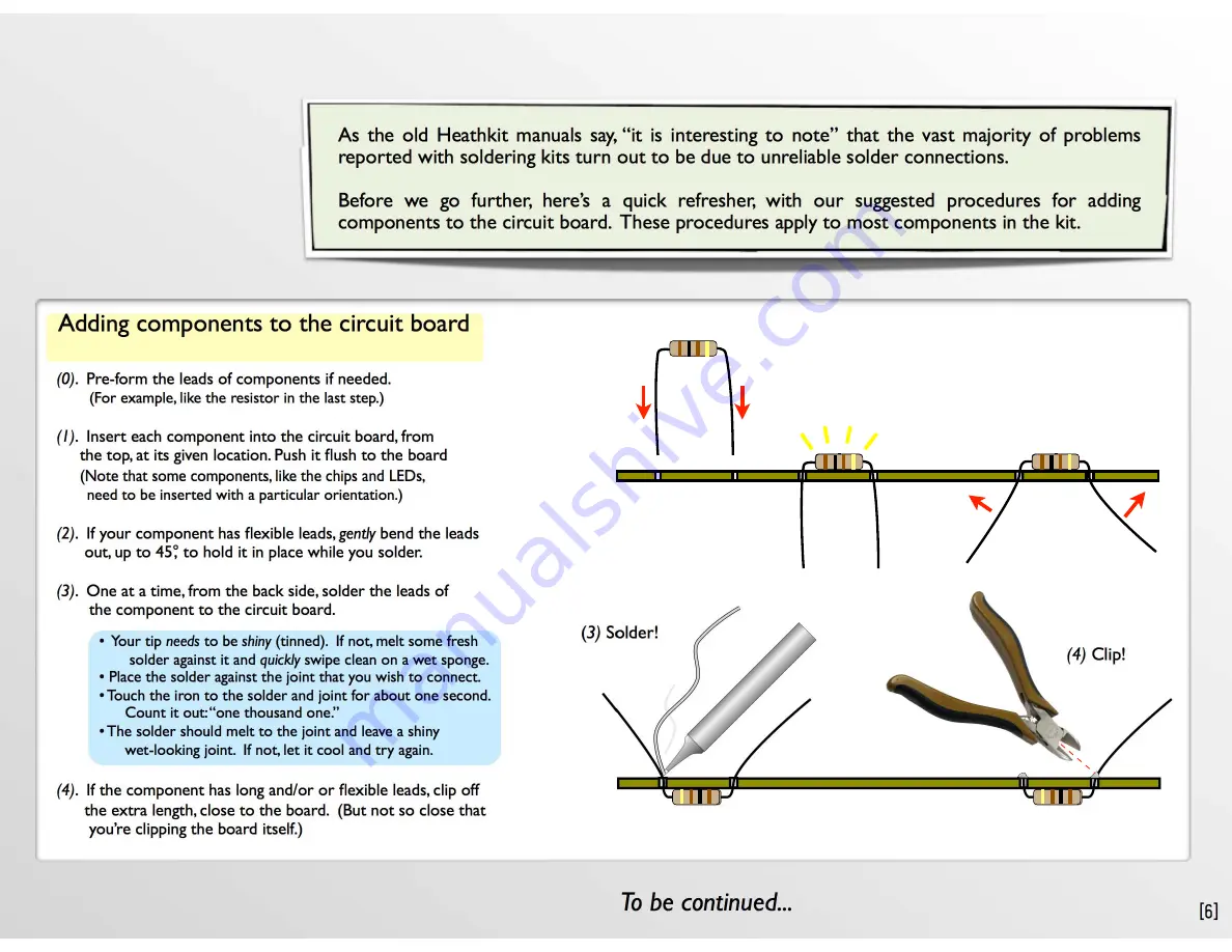
(0)
. Pre-form the leads of components if needed.
(For example, like the resistor in the last step.)
(1)
. Insert each component into the circuit board, from
the top, at its given location. Push it
fl
ush to the board
(Note that some components, like the chips and LEDs,
need to be inserted with a particular orientation.)
(2)
. If your component has
fl
exible leads,
gently
bend the leads
out, up to 45°, to hold it in place while you solder.
(3)
. One at a time, from the back side, solder the leads of
the component to the circuit board.
(4)
. If the component has long and/or or
fl
exible leads, clip off
the extra length, close to the board. (But not so close that
you’re clipping the board itself.)
• Your tip
needs
to be
shiny
(tinned). If not, melt some fresh
solder against it and
quickly
swipe clean on a wet sponge.
• Place the solder against the joint that you wish to connect.
• Touch the iron to the solder and joint for about one second.
Count it out: “one thousand one.”
• The solder should melt to the joint and leave a shiny
wet-looking joint. If not, let it cool and try again.
Adding components to the circuit board
As the old Heathkit manuals say, “it is interesting to note” that the vast majority of problems
reported with soldering kits turn out to be due to unreliable solder connections.
Before we go further, here’s a quick refresher, with our suggested procedures for adding
components to the circuit board. These procedures apply to most components in the kit.
To be continued...
(
3)
Solder!
(4)
Clip!
(1)
Insert!
(2)
Bend!
45°, max
Assembly Step 5 – Some tips on soldering
[Alpha Cloc k Five Assembly Guide]


