


6
7
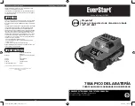
Model number JUS750CE
Contact us / 1-877-571-2391
Model number JUS750CE
Contact us / 1-877-571-2391
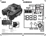
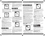
Press the Compressor Power
Button.
(Refer to the
“
Portable
Compressor
”
section.)
A beep will sound and the backlit LCD screen
will display the Battery Status Icon,
“
XXX
”
PSI
and the Compressor Icon. If no further actions
are taken after 1 minute, the unit will display
the Battery Status Icon and Battery Voltage
Indicator for 10 seconds before automatically
turning off.
Whenever the clamps are properly
connected to a battery
(refer to the
“
Jump Starter
”
section)
…
… a beep will sound and the backlit LCD
screen will display the Battery Status Icon,
Battery Voltage Indicator, the Clamp Icons,
and the
“
+
”
and
“
–
”
signs, as well as the
flashing Jump Starter Icon. The unit remains
on until the clamps are disconnected from
the battery.
If the Jump Starter Power Switch
is rotated to the on position and
the clamps are not connected to a
battery
(refer to the
“
Jump Starter
”
section)
…
... a two-second warning will sound every 10
seconds. The backlit LCD screen will display
the Battery Status Icon, Battery Voltage
Indicator, the Clamp Icons, and the
“
+
”
and
“
–
”
signs. The Alarm Icon and the Jump Starter
Icon will flash. The unit remains on until the
Jump Starter Power Switch is switched off
and then displays the battery status icon and
the voltage of digital display for 10 seconds
before automatic shut down.
If the clamp connections to the
battery’s positive and negative
terminals are reversed
(refer to the
“
Jump Starter
”
section)
…
… the backlit LCD screen will display the
Battery Status Icon, Battery Voltage Indicator,
and the Clamp Icons. The Alarm Icon, the
“
+
”
and
“
–
”
signs and the Reverse Polarity
Icons will flash and the unit will sound a
warning continuously until the clamps are
disconnected from the battery.
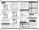
When the unit is charging
or recharging using the built-in
120 Volt AC Charger
(refer to the
“
Charging/Recharging
”
section)
…
… the backlight will turn on for 10 seconds
(only). The LCD screen will continue to display
the Battery Status Icon and Battery Voltage
Indicator. The bars on the Battery Status Icon
will change from empty to solid (bottom to
top) repeatedly.
Note:
The unit will automatically power off once ALL the functions are turned off.
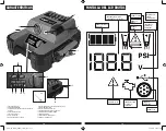
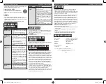
VIEWING BATTERY
STATUS
The Battery Status Icon and Battery Voltage Indicator indicate the battery charge level
as follows.
• If the battery charge level is at full capacity, four solid bars will display.
• If the battery is partially charged, two or three solid bars will display.
• If the battery is nearly empty, one solid bar will display. The unit should be charged
at this time.
• If the battery is completely empty, four blank bars will display. The unit MUST be
charged at this time or the unit’s built-in low voltage protection will activate. The empty
Battery Status Icon will flash for a short period of time before automatic shut down.
The unit will not operate until the battery is recharged.
CHARGING/RECHARGING
This unit is delivered in a partially charged state – you must fully charge it before using
it for the first time. Initial AC charge should be for 24 hours or until the Battery Status
Icon shows 4 solid bars.
Lead-acid batteries require routine maintenance to ensure a full charge and long battery
life. All
batteries lose energy from self-discharge over time and more rapidly at higher
temperatures. Therefore, batteries need periodic charging to replace energy lost through
self-discharge. When the unit is not in frequent use, manufacturer recommends the
battery should be recharged at least every 30 days and after each use.
CAUTION –
Risk of property damage: Failure to keep the battery charged will cause
permanent damage and result in poor jump starting performance.
IMPORTANT NOTES:
• Recharging the battery after each use will prolong battery life; frequent heavy
discharges between recharges and/or overcharging will reduce battery life.
• Make sure all other unit functions are turned off during recharging, as this can slow the
recharging process.
• If you know the unit is discharged, but the battery icon displays four solid bars as if the
unit is fully charged when connected to a charging power source, this may be due to
the internal battery having high impedance. The manufacturer suggests leaving the unit
charging for a period of 40 hours using the built-in AC charger before use.
Charging/Recharging Using the Built-In 120
Volt AC Charger and AC Extension Cord (not
included)
1. Lift the protective cover of the built-in 120 Volt AC Charger (refer to the “Features
section to locate). Connect an extension cord to the unit. Plug the other end of the
cord into a standard 120-volt AC wall outlet. When the unit is properly connected
to an AC power source, the LCD screen will display the following:
The bars on the Battery Status Icon represent the charge level of the unit’s internal
battery. The bars on the Battery Status Icon will change from empty to solid
(bottom to top) repeatedly to indicate the unit is charging. The backlight will turn on
for 10 seconds (only).
2. Charge for approximately 24 hours or until the Battery Status Icon shows 4 solid bars.
3. When charging is complete, unplug the AC extension cord from the AC outlet and
then disconnect it from the unit.
JUMP-STARTER
This unit is equipped with a jump starter power switch that allows energy to flow only
when proper connections are made to battery and frame.
A. For negative-grounded systems, connect the positive (red) clamp to the
positive ungrounded battery post and the negative (black) clamp to the vehicle
chassis or engine block away from the battery. Do not connect the clamp to
the carburetor, fuel lines or sheet-metal body parts. Connect to a heavy gauge
metal part of the frame or engine block.
B. For positive-grounded systems, connect the negative (black) clamp to the
negative ungrounded battery post and the positive (red) clamp to the vehicle
chassis or engine block away from the battery. Do not connect the clamp to
the carburetor, fuel lines or sheet-metal body parts. Connect to a heavy gauge
metal part of the frame or engine block.
IMPORTANT:
Make sure the Compressor Power Button has been turned off before
attempting to use the unit as a Jump Starter.
WARNING –
To reduce the risk of serious injury or property damage:
• Follow all safety instructions found in the “Specific Safety Instructions for Jump
Starters” section of this instruction manual.
• Never touch red and black clamps together. This can cause dangerous sparks, power
arcing, and/or explosion.
• If the clamps are connected incorrectly with regard to polarity, the unit will sound
a continuous alarm until the clamps are disconnected. The backlit LCD Screen will
display the Battery Status Icon, the Battery Voltage Indicator and the Clamp Icons. The
“+” and”–” signs above the Clamp Icons, the Arrow Icons and the Alarm Icon will flash.
The backlit LCD screen will display the following:
CAUTION:
The unit will suffer permanent damage if the Jump Starter Power Switch
is turned on while the clamps connected with reverse polarity. Disconnect the clamps
and reconnect to battery with correct polarity.
• If the Jump Starter Power Switch is turned on and the unit detects that the clamps are
not connected to a battery, a two-second warning will sound every 10 seconds. The
LCD screen will display the Battery Status Icon, the Battery Voltage Indicator, and the
Clamp Icons with the “+” and”–” signs. The Alarm Icon and the Jump Starter Icon will
flash. The backlit LCD screen will display the following:
• Turn off the Jump Starter Power Switch; connect the clamps to the battery, making
sure the clamps are connected with correct polarity; then turn the Jump Starter Power
Switch back on.
• Always disconnect the negative (black) jumper cable first, followed by the positive (red)
jumper cable, except for positive grounded systems.
PROCEDURE
Take the following steps, observing all cautions and warnings in the “Important Safety
Instructions” section at the front of this manual.
1. Turn off vehicle ignition and all accessories (radio, A/C, lights, connected cell
phone chargers, etc.). Place vehicle in “park” and set the emergency brake.
2. Make sure the jump-starter power switch is in the off position.
3. Remove jumper clamps from clamp tabs. Connect the red clamp first, then the
black clamp.
4. Procedure for jump-starting a NEGATIVE GROUNDED SYSTEM (negative
battery terminal is connected to chassis) (MOST COMMON)
4a. Connect positive (+) red clamp to vehicle battery’s positive terminal.
4b. Connect negative (–) black clamp to chassis or a solid, non-moving, metal
vehicle component or body part. Never clamp directly to negative battery
terminal or moving part. Refer to the automobile owner’s manual.
5. Procedure for jump-starting POSITIVE GROUND SYSTEMS
NOTE:
In the rare event that the vehicle to be started has a Positive Grounded System (positive battery
terminal is connected to chassis), replace steps 4a and 4b above with steps 5a and 5b, then
proceed to step 6.
5a. Connect negative (–) black clamp to vehicle battery’s negative terminal.
5b. Connect positive (+) red clamp to vehicle chassis or a solid, non-moving,
metal vehicle component or body part. Never clamp directly to positive battery
terminal or moving part. Refer to the automobile owner’s manual.
6. When the clamps are connected properly, the backlit LCD screen will display the
following to indicate the unit is ready to jump-start:
The Battery Status icon, Battery Voltage Indicator, Clamp Icons and the “+” and”–”
signs light solid. The jump starter icon will flash to indicate the clamps are properly
connected.
7. Turn the Jump-Starter Power Switch on. When the Jump-Starter Power Switch is
turned on, the Engine Icon lights solid indicating it is time to start the vehicle. Turn
on the ignition and crank the engine in 5-6 second bursts until engine starts. The
backlit LCD screen will display the following:
The Battery Status Icon, the Battery Voltage Indicator, Jump Starter Icon, Clamp
Icons and the “+” and”–” signs light solid to indicate the unit is jump-starting.
8. Turn the Jump-Starter Power Switch off.
9. Disconnect the negative (–) engine or chassis clamp first, then disconnect the
positive (+) battery clamp.
IMPORTANT:
Always turn the unit off when not in use. Recharge this unit fully after
each use.
CAUTION –
To reduce the risk of property damage:
• Vehicles that have on-board computerized systems may be damaged if vehicle battery
is jump-started. Before jump-starting this type of vehicle, read the vehicle manual to
confirm that external-starting assistance is advised.
• Excessive engine cranking can damage the vehicle‘s starter motor. If the engine fails
to start after the recommended number of attempts, discontinue jump-start procedure
and look for other problems that need to be corrected.
• If vehicle fails to start, turn off the ignition, turn off the Jump-Starter Power Switch,
disconnect the jump-start system’s leads and contact a qualified technician to
investigate why the engine did not start.
LED AREA LIGHT
The built-in LED Area Light consists of two LEDs on of the front of the unit. It is
controlled by the Area Light Power Button on the control panel (refer to the “Features”
to locate).
1. Press the Area Light Power Button once to turn the light on.
2. Press the Area Light Power Button again to turn the area light off.
When the Area Light Power Button is pressed to turn it on, a beep will sound. The
backlit LCD screen will turn on for 10 seconds (only) and will then continuously display
the Battery Status Icon and the Battery Voltage Indicator.
Periodically check the unit’s battery status on the backlit LCD screen. Four solid bars in
the battery icon indicates a full battery. When the battery level is nearly empty with only
one solid bar or completely empty with 4 empty bars, the unit must be recharged at this
time or the unit’s built-in low voltage protection will activate. The empty Battery Status
Icon will flash for a short period of time before automatic shut down.
IMPORTANT:
Make sure the Area Light is turned off when the unit is being recharged
or stored.
JUS750CE_Manual_ENSP_042820.indd 6-7
JUS750CE_Manual_ENSP_042820.indd 6-7
4/29/2020 2:16:36 PM
4/29/2020 2:16:36 PM


