


EZN1160/1260/1360
3
3.
Physical Description
1
2
3
4
5
6
8
9
Front Module
Rear Module
10
7
No. Item Name
Descriptions
1
Light Sensor
Detects lights.
2
IR LEDs
8 IR LEDs for infrared illumination in night vision applications.
3
Lens
Fixed lens.
4
Video Test Output
Connects to a handheld test monitor for adjusting camera view.
5
Reset Button
Resets all configurations to the factory default settings.
6
Micro SD / SDHC Slot
Insert a micro SD / SDHC card. See
4.3 Inserting a Micro SD Card.
7
Spare Terminal Block
For connecting to power or alarm I/O. See
3.1 Cables and Terminal Block
.
8
Front Cover
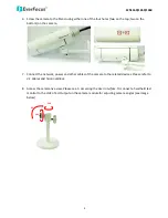
Remove the cover for connecting to a handheld test monitor.
9
Sunshield
Protect the camera from the direct rays of the sun.
10 Base Cover
Remove the cover for inserting a micro SD card.
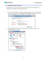
3.1
Cables and Terminal Block
The cables provide connections for Network, power and alarm input / output. The wires are illustrated
and defined below.
Alarm Input / Output
12 VDC / 24 VAC
LAN / PoE Cable
Pin Assignment for Alarm I/O
4 3 2 1
Alarm Out Pin 1: Alarm COM (-)
Pin 2: Alarm Out (+)
Alarm In
Pin 3: Alarm In (+)
Pin 4: Ground (-)
Spare Terminal Block on the Rear Module
To open the Rear Module, please refer to Step 1 to 3 in
4.3 Inserting a Micro SD Card.
6 5 4 3 2 1
Power
Pin 1: 12 VDC+ / 24 VAC+
Pin 2: 12 VDC- / 24 VAC-
Alarm Out
Pin3: Alarm COM (-)
Pin4: Alarm Out (+)
Alarm In
Pin5: Alarm In (+)
Pin6: Ground (-)


