background image

EverExceed Smart IT Cabin


Solution User Manual 

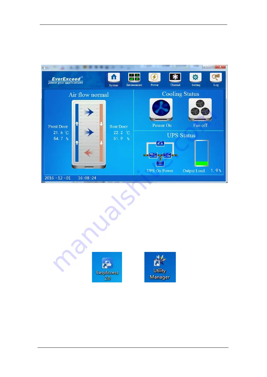
connect local network. Moreover, the users can connect multiple devices   

simutaneously. The remote interface is the same as the touch screen display, 

as shown in figure 4-23. 


Figure 4-23 Remote Control 


4.3.1 The way of remote control   

Before the remote control, you need to install Easyacess 2.0 and EsayBuilder 

Pro software on your PC, then login the Easyaccess with Domain account and 

password. Soft waft icon shown in Figure 4-24 


Figure 4-24 Soft waft icon 

Step 1: Enter the Web setting submenu under the Setting menu of the touch 

screen, click “ Easy Access 2.0” Button, the page shown in Figure 4-25. Then 

click start, it will show “ success” if connect successfully.   

www.everexceed.com                                                                    

25

  / 

32


Содержание Smart IT Cabin SC10000

Страница 1: ...EverExceed Smart IT Cabin Solution User Manual EverExceed Industrial Co Ltd www everexceed com...

Страница 2: ...ructions 8 2 2 2 Outside machine wiring diagram Figure 2 4 8 2 2 3 Connecting Copper Pipes 8 Chapter 3 Operation instructions 9 3 1 Check before Startup 9 3 2 Startup 10 3 3 Power off 10 Chapter 4 Ope...

Страница 3: ...emote control 24 Chapter 5 Maintenance 29 5 1 SAFETY INSTRUCTION 29 5 2 AC System Maintenance 29 5 3 UPS Power Distribution System Maintenance 31 5 4 Trouble shooting 31 EverExceed Smart IT CabinSolut...

Страница 4: ...ard field installation no need of raised floor and integrated delivery shorten the delivery period to great extent The monitoring management with all range of EverExceed products plug and play it also...

Страница 5: ...and so on provide centralized monitoring platform for computer room environment Highly integrated and space saving one standard cabinet provides stable operation conditions for all IT devices only ca...

Страница 6: ...and energy saving Air conditioning system Air conditioner Cooling the electronic devices inside the cabinet actively Small sized precision environment control system keep the environment in the cabin...

Страница 7: ...proper operation may cause physical injury or death and damage to the equipment 2 The center of gravity of Smart IT Cabin is forward inclined during conveying process not to adjust the bearing positio...

Страница 8: ...ponent Range of dimension mm Weight Unit kg H W D Cabinet component with package 2150 720 1400 450kg Carrying The user needs to carry the cabinets closed frames and AC indoor unit to the nearest place...

Страница 9: ...t and the bagging package materials 2 Remove the feed pressure plate Use a sleeve or a moveable wrench to remove the fixing screws on the pallet and remove the pressure plate as shown in Figure 2 3 Fi...

Страница 10: ...dity corrosive gases in harsh environments Among them the ambient temperature shall not be higher than 45 the humidity shall not exceed 85 and starting running voltage shall not exceed 10 of rated vol...

Страница 11: ...acement of pipe system evacuation and charging with refrigerant only when pipeline is too long 3 Give considerations to pipeline pressure drop oil return to the compressor to avoid oil leakage and clo...

Страница 12: ...e wrench can damage the coupling copper lines easily Chapter 3 Operation instructions 3 1 Check before Startup Check the following before startup of Smart IT Cabin 1 Check whether the AC pipe system i...

Страница 13: ...l turn on as shown in Figure 4 3 a Press the ON SILENCE key for above 1s and wait about 30s the UPS will switch to inverter standby mode and the INVERTER indicator will blink When the UPS has output t...

Страница 14: ...ter 4 Operation on Display Panel 4 1 The Smart IT Cabin Home page The Smart IT Cabin Homepage is shown in Figure 4 1 Figure 4 1 Home page On the Smart IT Cabin Homepage the menu items include System E...

Страница 15: ...items 4 2 1 Main information of Smart IT Cabin On the display screen click the System menu at the upper part the system page will appear displaying air flow status cabinet cold aisle temperature hot...

Страница 16: ...own in Figure 4 4 The curve displays the front door temperature and rear door temperature within one hour in real time the right part displays front door on off status rear door on off status and wate...

Страница 17: ...g valve The default valves of temperature alarm are as follows The alarm upper limit of front door temperature sensor is 35 C and the alarm lower limit is 0 C the alarm upper limit of rear door temper...

Страница 18: ...page the status page will appear as shown in Figure 4 7 Figure 4 7 Power Status Page 1 Figure 4 8 Power Status Page 2 Click the setting submenu in the left part the setting page appears as shown in F...

Страница 19: ...n in Figure 4 10 You can realize on off control over each place of the PDU through clicking the OFF ON icon When the icon s green and displaying ON status it indicates that the PDU output status is ON...

Страница 20: ...Figure 4 11 Thermal Status Page Click the thermal submenu at the left part the thermal page will appear as shown in Figure 4 12 You can click the OFF ON icon in the Power On Off filed to realize AC o...

Страница 21: ...panel click the Setting menu on top of the page six submenues appear including Password setting System Information Language setting Web setting Alarm Telephone Setting Message Alarm Setting Password...

Страница 22: ...tting System Information Click the Information submenu under the Setting menu the page shown in Figure 4 14 The system name hardware version software version and product serial number available checke...

Страница 23: ...e 4 15 Chinese English available choice other language available to add as option Figure 4 15 System Information Web Setting Click the Web setting submenu under the Setting menu the page shown in Figu...

Страница 24: ...er Setting Click the Alarm Telephone setting submenu under the Setting menu the page shown in Figure 4 17 You can set 5 telephone number enter number of the Alarm Telephone and tick on the right side...

Страница 25: ...age Alarm Setting submenu under the Setting menu the page shown in Figure 4 18 Figure 4 18 SMS alarm setting Message Alarm setting including all the alarm contents if need any Alarm item tick in behin...

Страница 26: ...be an alarm sound If you want to turn off the alarm sound click the Alarm button Click the Log menu on the submenu you can check and view current Alarm Alert as shown in Figure 4 20 You can view hist...

Страница 27: ...his system provides a new solution for remote monitoring No matter where the equipment is located its operation can be monitored as long as Internet is available so the trouble or faulty can be known...

Страница 28: ...emote control Before the remote control you need to install Easyacess 2 0 and EsayBuilder Pro software on your PC then login the Easyaccess with Domain account and password Soft waft icon shown in Fig...

Страница 29: ...ep 2 Login on EasyAccess 2 0 software on your PC enter the Domain account name and password the page shown in Figure 4 26 Figure 4 26 Login Page Step 3 After login account successfully the page shown...

Страница 30: ...7 connect interface Step 4 After on line click icon to enter the remote control page and then click the black dot as shown in Figure 4 30 you can enter the major interface to realize the remote contro...

Страница 31: ...EverExceed Smart IT Cabin Solution User Manual Figure 4 29 connect interface Figure 4 30 connect interface 28 32 www everexceed com...

Страница 32: ...safety instructions will endanger personnel safety and environment 4 Unsuitable components will lead to performance decrease or equipment shutdown it is commended to use the components made by EverExc...

Страница 33: ...ed air should be blown at the reversed airflow direction In winter do not let snow to accumulate around the side or underneath the condenser Check for bent or damaged fins and simply repair them if ne...

Страница 34: ...y is discharging When mains is normal the battery should not discharge if the UPS operates in Battery mode find out the reason such as mains failure battery test operator intervention and so on Note R...

Страница 35: ...eck that the connection of the condensate water pipes is reliable PDU over load alarm PDU exceeds the load setpoint Check the actual load power of single PDU PDU less than the limit of load setpoint C...

Отзывы: