


SC
3012
SC
3010
Horizontal/Vertical Orientation
8
OPERATION
3.
OPERATION
3.1.
First Steps
Rear Connections & DIP Switches
Check the package components (loudspeaker, user‘s manual, power cord,
rubber feet);
Check the voltage setting (“3.15. Mains Voltage Selector” on page 15).
Check the setting of the DIP Switches (variable).
Connections: there are two input connectors on the rear side. These allow
the connection of balanced sources with XLR connectors or unbalanced
sources with RCA connectors.
•
Pin assignment XLR: 1 = Shield, 2 = hot (+), 3 = cold(-).
•
Pin assignment RCA: Center conductor = Signal, Ring = Shield.
Both analog inputs can be used simultaneously, whereby the signals are
summed.
Depending on the setting of the Max. Input DIP switch on the rear panel,
the maximum level of the source signal should not 7 dBu or
+22 dBu (see “3.14. DIP Switches” on page 15, Max. Input). If the input is
overloaded the LED ring will start blinking.
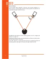
3.2.
Horizontal/Vertical Orientation
The SC3010 and SC3012 can be used in horizontal or vertical position