EVCO S.p.A.
c-pro 3 giga | Hardware manual ver. 3.0 | Code 144CP3GI304
page 1 of 44
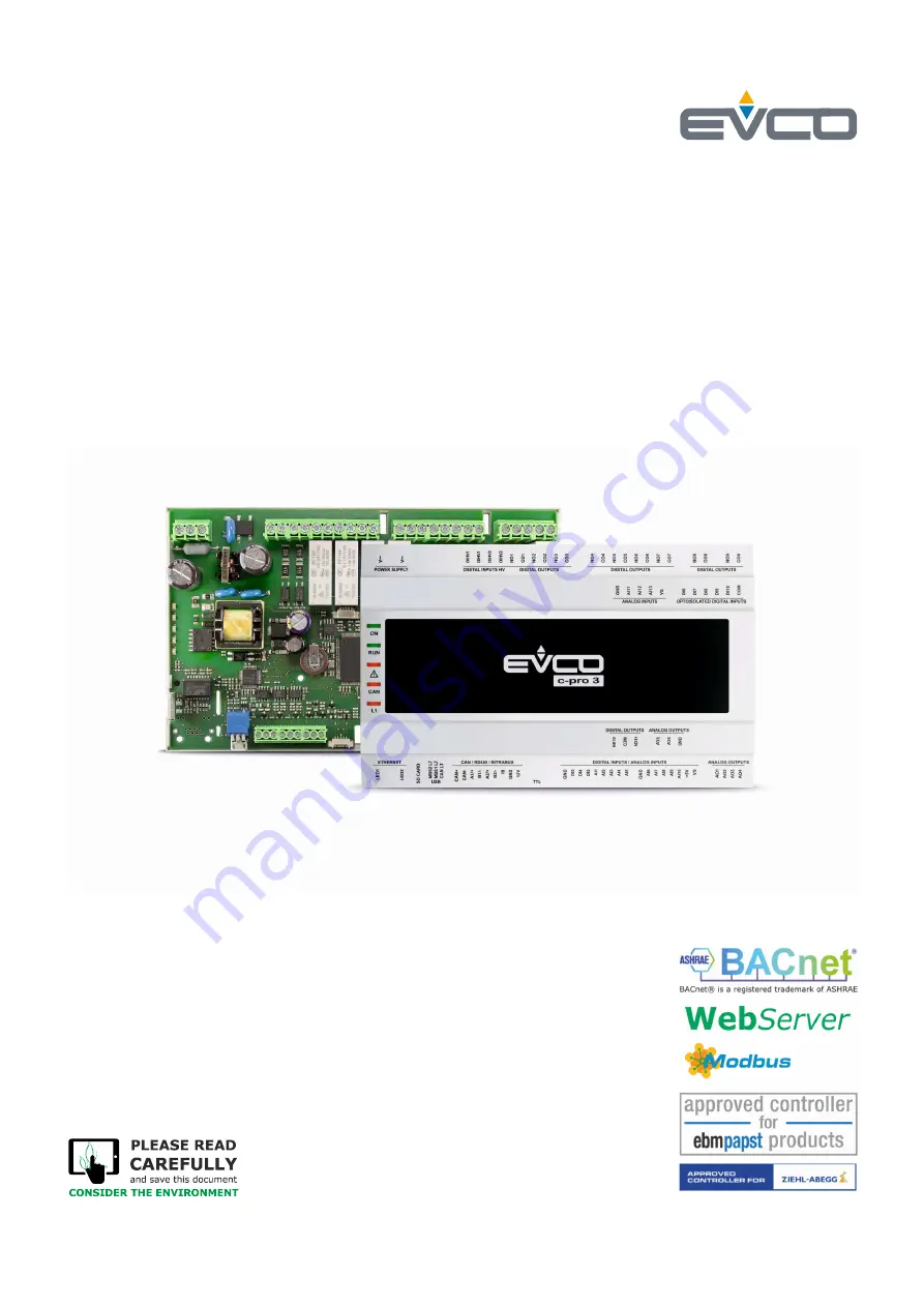
c-pro 3 giga
Programmable controllers
(up to 43 I/O)
Hardware manual | ENGLISH
Code 144CP3GI304
Страница 1: ...EVCO S p A c pro 3 giga Hardware manual ver 3 0 Code 144CP3GI304 page 1 of 44 c pro 3 giga Programmable controllers up to 43 I O Hardware manual ENGLISH Code 144CP3GI304 ...
Страница 2: ...tallation and before using the device and take all the prescribed precautions Keep this document with the device for future reference Only use the device in the ways described in this document The device must be disposed of according to local regulations governing the collection of electrical and electronic equipment ...
Страница 3: ...al informazion 25 8 LEDS 26 8 1 Device signalling LEDS 26 8 2 Unipolar stepper electronic expansion valve signalling LEDS 26 9 CONFIGURATION PARAMETERS 27 9 1 Configuration parameters of the Info menu 27 9 2 Configuration parameters of the Parameters menu 27 9 3 Configuration parameters of the CAN Bus sub menu of the Networks menu 31 9 4 Configuration parameters of the UART1 sub menu of the Networ...
Страница 4: ...ems The application software can be set up quickly and intuitively thanks to the UNI PRO 3 integrated development environment The NODE versions have an Ethernet port for the use of MODBUS TCP BACnet IP and Web Server all the versions have a data logging function Some controllers have 2 built in drivers for unipolar stepper type expansion valves In the 10 DIN module blind version the controller is ...
Страница 5: ... or dry contact digital input 5 5 8 8 8 PTC NTC Pt 1000 0 5 V 0 10 V 0 20 mA 4 20 mA or dry contact digital input 5 5 8 8 8 DIGITAL INPUTS Dry contact 4 Dry contact and for pulse trains up to 2 KHz 3 3 3 3 3 High voltage 2 2 2 2 2 ANALOGUE OUTPUTS 0 10 V PWM 4 4 8 4 4 DIGITAL OUTPUTS ELECTRO MECHANICAL RELAYS 2 A SPST 2 2 6 6 2 3 A SPST 5 5 5 5 5 3 A SPDT 1 1 1 1 1 5 A SPST 2 8 A SPST 1 1 2 2 1 CO...
Страница 6: ...pro 3 giga Hardware manual ver 3 0 Code 144CP3GI304 page 6 of 44 OPTIONAL FEATURES USING ADDITIONAL ACCESSORIES BLE connectivity using the EVIF25TBX module Wi Fi connectivity using the EVIF25TWX or EVIF25SWX module ...
Страница 7: ... NTC Pt 1000 0 5 V 0 10 V 0 20 mA 4 20 mA or dry contact digital input 5 5 8 8 8 DIGITAL INPUTS Dry contact Dry contact and for pulse trains up to 2 KHz 3 3 3 7 3 High voltage 2 2 2 2 2 ANALOGUE OUTPUTS 0 10 V PWM 4 4 8 4 4 DIGITAL OUTPUTS ELECTRO MECHANICAL RELAYS 2 A SPST 2 2 6 6 2 3 A SPST 5 5 5 5 5 3 A SPDT 1 1 1 1 1 5 A SPST 2 8 A SPST 1 1 2 2 1 COMMUNICATION PORTS TTL MODBUS 1 1 1 1 1 INTRAB...
Страница 8: ...CP3GI304 page 8 of 44 OPTIONAL FEATURES USING ADDITIONAL ACCESSORIES BLE connectivity using the EVIF25TBX module Wi Fi connectivity using the EVIF25TWX or EVIF25SWX module NOTES 1 the BACnet communication protocol is an alternative to the Web Server function ...
Страница 9: ...manual ver 3 0 Code 144CP3GI304 page 9 of 44 3 MEASUREMENTS AND INSTALLATION 3 1 Measurements of open frame models Measurements are expressed in mm inches 3 2 Measurements of models with housing Measurements are expressed in mm inches ...
Страница 10: ...lip fully in INSTALLATION PRECAUTIONS ensure that the working conditions are within the limits stated in the TECHNICAL SPECIFICATIONS section do not install the device close to heat sources equipment with a strong magnetic field in places subject to direct sunlight rain damp excessive dust me chanical vibrations or shocks in compliance with safety regulations the device must be installed properly ...
Страница 11: ...BACnet IP 8 Micro switch for fitting the termination resistor of the RS 485 network connected to the RS 485 MODBUS slave port fitting the termination resistor of the RS 485 network connected to the RS 485 MODBUS master slave BACnet MS TP port fitting the termination resistor of the CAN network 9 USB port 10 CAN port RS 485 MODBUS master slave BACnet MS TP port RS 485 MODBUS slave port and INTRABUS...
Страница 12: ...the plus controllers Digital outputs electro mechanical relays 11 14 19 Only available in the plus controllers Digital output electro mechanical relay 10 20 Only available in the U EEV controllers Output unipolar stepper electronic expansion valve 2 engine control 20 Only available in the U EEV controllers Output unipolar stepper electronic expansion valve 1 engine control 22 Only available in the...
Страница 13: ...le in the basic controllers CONN DESCRIPTION V device power supply 115 230 VAC V device power supply 115 230 VAC CONN DESCRIPTION DIHV1 high voltage digital input DI1 DIHV2 high voltage digital input DI2 COM common contact high voltage digital inputs CONN DESCRIPTION NO1 K1 digital output normally open contact 3 A res 250 VAC CO1 K1 digital output common contact NO2 K2 digital output normally open...
Страница 14: ...O 3 16 version uses a standard BACnet B ASC device profile Management of the Scheduler and Calendar objects is not included in this profile while it is in the B AAC profile CONN DESCRIPTION GND reference GND DI3 digital input 3 dry contact and for pulse trains up to 2 KHz DI3 DI4 digital input 4 dry contact and for pulse trains up to 2 KHz DI4 DI5 digital input 5 dry contact and for pulse trains u...
Страница 15: ...0 can also be configured for dry contact digital input 5V 0 5 V ratiometric transducers power supply 5 VDC VS transducers power supply 13 VDC CONN DESCRIPTION AO1 analogue output 1 for 0 10 V or PWM signal AO2 analogue output 2 for 0 10 V or PWM signal AO3 analogue output 3 for 0 10 V or PWM signal AO4 analogue output 4 for 0 10 V or PWM signal 5 2 Further connectors only available in the plus con...
Страница 16: ...15 analogue input 15 for PTC NTC or Pt 1000 probes 0 5 V 0 10 V 0 20 mA or 4 20 mA transducers AI15 can also be configured for dry contact digital input AI16 analogue input 16 for PTC NTC or Pt 1000 probes 0 5 V 0 10 V 0 20 mA or 4 20 mA transducers AI16 can also be configured for dry contact digital input 5V 0 5 V ratiometric transducers power supply 5 VDC VS transducers power supply 13 VDC CONN ...
Страница 17: ...lectronic expansion valve 1 engine control CONN DESCRIPTION REF power supply engine unipolar stepper electronic expansion valve 2 12 VDC 260 mA max winding OUT4 output 4 unipolar stepper electronic expansion valve 2 engine control OUT3 output 3 unipolar stepper electronic expansion valve 2 engine control OUT2 output 2 unipolar stepper electronic expansion valve 2 engine control OUT1 output 1 unipo...
Страница 18: ... for dry contact digital input 5V 0 5 V ratiometric transducers power supply 5 VDC VS transducers power supply 13 VDC 5 4 Fitting the termination resistor of the RS 485 networks and the CAN network To fit the termination resistor of the RS 485 network connected to the RS 485 MODBUS slave port place the MBS1LT micro switch in position ON To fit the termination resistor of the RS 485 network connect...
Страница 19: ...EVCO S p A c pro 3 giga Hardware manual ver 3 0 Code 144CP3GI304 page 19 of 44 5 5 Example of electrical connection for basic controllers ...
Страница 20: ...EVCO S p A c pro 3 giga Hardware manual ver 3 0 Code 144CP3GI304 page 20 of 44 5 6 Example of electrical connection for plus controllers ...
Страница 21: ...he device is moved from a cold to a warm place humidity may cause condensation to form inside Wait for about an hour before switching on the power make sure that the supply voltage electrical frequency and power are within the set limits See the section TECHNICAL SPECIFICATIONS disconnect the power supply before carrying out any type of maintenance do not use the device as a safety device for repa...
Страница 22: ...us CAN screen 6 Touch the ENTER key the display will show the main menu 7 Touch the UP or DOWN key to select the Net works menu 8 Touch the ENTER key 9 Touch the UP or DOWN key to select the CAN BUS sub menu 10 Touch the ENTER key to access the menu the display will show the Input Password screen 11 Touch the ENTER key again 12 Touch the UP or DOWN key to set 19 13 Touch the ENTER key the display ...
Страница 23: ...age menu 28 Touch the ENTER key 29 Touch the UP or DOWN key to set the language 30 Touch the ENTER key To set the date and time 27 From point 26 touch the UP or DOWN key to select the date and time 28 Touch the ENTER key 29 Touch the UP or DOWN key to set the value 30 Touch the LEFT or RIGHT key to select another field 31 Touch the UP or DOWN key to set the value 32 Touch the ENTER key To copy the...
Страница 24: ...Touch the UP or DOWN key to select Restore from the key 30 Touch the ENTER key it will begin copying the configuration This normally takes a couple of seconds If it fails to copy the system alarm LED will light up and the message Err will appear in the configura tion parameter Key Par 31 Disconnect the USB flash drive from the USB port of the device 32 Disconnect the device from the mains 33 Power...
Страница 25: ...ent must keep the software enabling at a low value to allow a first data exchange that correctly sets the valve data Subsequently the application must enable the valve and pilot a resynchronization Only at this point is the valve ready to operate according to the desired adjustment To protect the valve mechanics it is necessary to distinguish two types of resynchronization which differ in the numb...
Страница 26: ...n Block Libraries system alarm activated that cannot be reset using the application software access to the external FLASH memory system alarm with automatic reset activated system alarm with manual reset activated CAN device configured to com municate via CAN with an other device but communica tion non established CAN communication estab lished but not entirely correct CAN communication estab lish...
Страница 27: ...ly parameter date and time the application project was last compiled 9 2 Configuration parameters of the Parameters menu PARAMETER MIN MAX U M DEF DESCRIPTION AI1 NTC type of probe analogue input 1 PTC PTC probe NTC NTC probe PT1000 Pt 1000 probe NTCK2 type 2 NTC probe NTCK3 type 3 NTC probe RESIST electrical resistance reading AI2 NTC type of probe analogue input 2 PTC PTC probe NTC NTC probe PT1...
Страница 28: ... V ratiometric transducer 0 10V 0 10 V transducer PT1000 Pt 1000 probe NTCK2 type 2 NTC probe NTCK3 type 3 NTC probe RESIST electrical resistance reading AI9 NTC type of probe analogue input 9 PTC PTC probe NTC NTC probe 0 20mA 0 20 mA transducer 4 20mA 4 20 mA transducer 0 5V 0 5 V ratiometric transducer 0 10V 0 10 V transducer PT1000 Pt 1000 probe NTCK2 type 2 NTC probe NTCK3 type 3 NTC probe RE...
Страница 29: ... 5 V ratiometric transducer 0 10V 0 10 V transducer PT1000 Pt 1000 probe NTCK2 type 2 NTC probe NTCK3 type 3 NTC probe RESIST electrical resistance reading AI16 NTC type of probe analogue input 16 PTC PTC probe NTC NTC probe 0 20mA 0 20 mA transducer 4 20mA 4 20 mA transducer 0 5V 0 5 V ratiometric transducer 0 10V 0 10 V transducer PT1000 Pt 1000 probe NTCK2 type 2 NTC probe NTCK3 type 3 NTC prob...
Страница 30: ...N coefficient of analogue input 4 filter AI5 filter OFF ON ON coefficient of analogue input 5 filter AI6 filter OFF ON ON coefficient of analogue input 6 filter AI7 filter OFF ON ON coefficient of analogue input 7 filter AI8 filter OFF ON ON coefficient of analogue input 8 filter AI9 filter OFF ON ON coefficient of analogue input 9 filter AI10 filter OFF ON ON coefficient of analogue input 10 filt...
Страница 31: ...ents of the network when the time set by this parameter has elapsed with no CAN communication with an element the element is disabled Network Node 1 0 32 127 1 99 address of remote CAN nodes that is of the other elements in the net work example for 1 2 1 node 2 node address TSEG1 unused TSEG2 unused SJW unused BTR unused Status read only parameter CAN machine status INIT initialisation STOPPED sto...
Страница 32: ...ing of the request is con sidered to have failed and the next request is sent this is important only when the communication protocol is MODBUS master 9 5 Configuration parameters of the UART2 sub menu of the Networks menu The parameters are only visible if the application software is set up for the RS 485 MODBUS slave port to be configured to support the MODBUS communication proto col PARAM MIN MA...
Страница 33: ...nable password to access level 1 OFF it is not necessary to set a password to access level 1 ON it is necessary to set a password to access level 1 Level 2 32768 32768 0 value of password to access level 2 ON enable password to access level 2 OFF it is not necessary to set a password to access level 2 ON it is necessary to set a password to access level 2 Level 3 32768 32768 0 value of password to...
Страница 34: ...tage of the 0 20 mA 4 20 mA and 0 10 V transducers OK no error ERR error due to voltage outside range MATH read only parameter math status OK no error ERR error due to overflow underflow dividing by zero or NaN KEY PAR read only parameter outcome of upload or download of the application software or configura tion parameters using the USB flash drive OK operation successfully completed ERR operatio...
Страница 35: ... unipolar stepper type expansion valve 1 position step EEV1 Alarm Valve error read only parameter unipolar stepper type expansion valve 1 alarm status 0 not configured 1 configured 2 in error EEV1 Step rate read only parameter unipolar stepper type expansion valve 1 step rate step s EEV1 Mode valve driving mode read only parameter unipolar stepper type expansion valve 1 driving mode 0 Full step 2p...
Страница 36: ...Full step 1phOn 2 Half step 3 Half step 4 Half step 5 Half step 6 Half step 7 Half step 8 Half step 9 Half step EEV2 Duty duty cycle read only parameter unipolar stepper type expansion valve 2 duty cycle EEV2 Working current read only parameter unipolar stepper type expansion valve 2 working current mA EEV2 Holding current read only parameter unipolar stepper type expansion valve 2 holding current...
Страница 37: ...3GI304 page 37 of 44 9 12 Configuration parameters of the Debug menu PARAM MIN MAX U M DEF DESCRIPTION ModBus 1 read only parameter unused ModBus 2 read only parameter unused IntraBus read only parameter unused NOTES 1 press the RIGHT key to view the parameter ...
Страница 38: ...25 Allows a USB flash drive to be connected Length 2 m 3 28 ft 10 3 RS 485 USB serial interface EVIF20SUXI Makes it possible to connect to the Parameters Manager setup software sys tem 10 4 INTRABUS RS 485 serial interface EVIF22ISX Makes it possible to convert the INTRABUS signal into an RS 485 MODBUS signal 10 5 EVlink TTL BLE module EVIF25TBX Makes BLE connectivity through the TTL possible 10 6...
Страница 39: ...Fi connectivity through the RS 485 possible 10 8 USB flash drive EVUSB4096M For uploading and downloading data 4 GB of memory 10 9 Connection kit CJAV47 Allows cabling in standard controllers with housing 10 10 Connection kit CJAV52 Allows cabling in plus controllers 10 11 Connection kit CJAV56 Allows cabling in U EEV controllers ...
Страница 40: ... 8 ft Analogue inputs 10 m 32 8 ft Auxiliary power supply and 0 5 V ratiometric transducer power supply 10 m 32 8 ft Digital inputs 10 m 32 8 ft Unipolar stepper electronic expansion valves driver 3 m 9 84 ft Analogue outputs 0 10 V 10 m 32 8 ft PWM analogue outputs 1 m 3 28 ft Digital outputs 100 m 328 ft INTRABUS port 10 m 32 8 ft RS 485 MODBUS port 1 000 m 3 280 ft USB port 1 m 3 28 ft CAN port...
Страница 41: ... F Resolution 1 C 1 F Precision 2 5 C 0 5 V transducers Input resistance 10 KΩ Resolution 0 01 V Precision 50 mV 0 10 V transducers Input resistance 10 KΩ Resolution 0 01 V Precision 50 mV 0 4 20 mA transducers Input resistance 200 Ω Resolution 0 01 mA Precision 0 1 mA Power supply remote user interfaces 13 VDC 20 10 150 mA max Power supply transducers 13 VDC 20 10 100 mA max 40 mA max for plus co...
Страница 42: ...n between the powered parts and the SELV circuits reinforced insulation between group 1 of relay outputs K1 K3 and the high voltage digital inputs DIHV1 and DIHV2 main insulation between the powered parts of opposite polarity line neutral Type 1 or Type 2 actions Type 1 Additional features of Type 1 or Type 2 actions C Communications ports 1 TTL MODBUS port 1 INTRABUS port RS 485 MODBUS master sla...
Страница 43: ...ctual Property Rights Code CPI EVCO imposes an absolute ban on the full or partial reproduction and disclosure of the content other than with the express approval of EVCO The customer manufacturer installer or end user assumes all responsibility for the configuration of the device EVCO accepts no liability for any possible errors in this document and reserves the right to make any changes at any t...
Страница 44: ...EVCO S p A c pro 3 giga Hardware manual ver 3 0 Code 144CP3GI304 page 44 of 44 EVCO S p A Via Feltre 81 32036 Sedico BL ITALY phone 39 0437 8422 fax 39 0437 83648 email info evco it web www evco it ...