Page 59/72
October 2019
W11E | Operation manual
Cooling
It is recommended that the Controller is assembled to a flat, free of paint surface preferably lightly coated with a
thermal transfer compound using the 4 holes provided. Ideally, this surface will provide maximum heat dissipation
and ensure full rated power output. When designing a cooling system, please refer to the following steps:
1.
Apply thermal grease to the Controller before mounting for better cooling effect.
2.
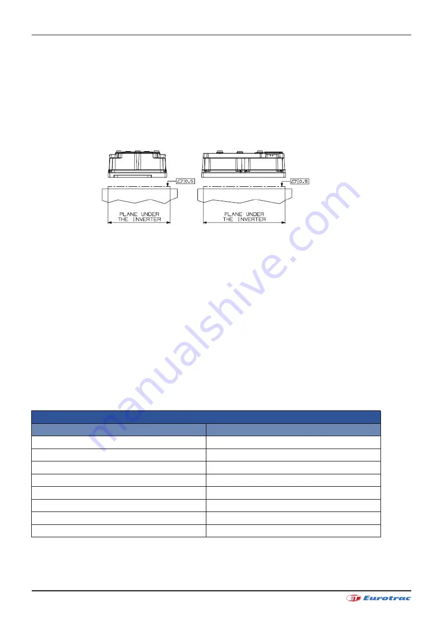
The Controller is cooled by the surface contact to the vehicle body, so it is important to pay much attention to
the flatness and the roughness of the surface of the vehicle frame where it is mounted. The roughness Rz
should be between 1.6
μ
m and 3.2
μ
m, while the planarity of the surface should be under 0.5mm, as shown in
the following image:
Planarity specifications for the AC-M2 with aluminium baseplate.
3.
Any airflow around the controller will further enhance the thermal performance.
4.
Additional heatsink could be necessary to meet the desired continuous ratings. The heat sink material and
system should be sized on the performance requirement of the machine. We recommend ambient
temperature air to be directed over the heatsink fins to maintain heatsink temperature below 75 °C.
5.
In systems where either ventilation is poor, or heat exchange is difficult, forced air ventilation should be used.
Clearances
For all AC-M2 models 50 mm clearances in front of and behind the AC-M2 are required for airflow; 50 mm clearance
above the AC-M2 is required for installation/removal of interface connectors and wiring.
6.2
Power Terminals
Wiring
The Controller has eight Power Terminals, which are clearly marked on Controller’s body as B+, B-, U1, V1, W1, U2,
V2 and W2 (See “AC – M2 General View”).
The recommended screw torque for fixing the Power Terminals is 6.4 Nm. This value is reported on the label placed
on the cover, exceeding the recommended value may cause damages.
Power Terminals on Controller
Terminal
Meaning
B+
Positive Battery coming from the Main Contactor
B- Negative
Battery
U1 U1
Motor
Phase
V1
V1 Motor Phase
W1
W1 Motor Phase
U2 U2
Motor
Phase
V2
V2 Motor Phase
W2
W2 Motor Phase
Содержание W11E
Страница 26: ...Page 26 72 October 2019 W11E Operation manual ...
Страница 35: ...Page 35 72 October 2019 W11E Operation manual 3 4 Troubleshooting 3 4 1 Kinetic energy reduction ...
Страница 36: ...Page 36 72 October 2019 W11E Operation manual 3 4 2 Drive axle ...
Страница 37: ...Page 37 72 October 2019 W11E Operation manual 3 4 3 Brake system ...
Страница 38: ...Page 38 72 October 2019 W11E Operation manual 3 4 4 Lithium battery ...
Страница 39: ...Page 39 72 October 2019 W11E Operation manual FIGURE 1 W11E HYDRAULIC SCHEMATIC ...
Страница 40: ...Page 40 72 October 2019 W11E Operation manual FIGURE 2 ELECTRICAL SCHEMATIC ...


