PC300 User Guide
HA 026773
Page 3 of 4
Issue 1.3 June 2000
User Wiring
Slot 1
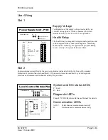
Supply Voltage
Configuration of the supply voltage is selected by an
external wiring option. A link is necessary between
terminals 10 and 11 for 85 to 132 V ac operation.
Health Relay
The health relay is energised during normal operation, and
is de-energised if the system watchdog fails. Watchdog
failure can be caused by the applications program failing
to run correctly of a system hardware failure.
Slot 2
Commissioning is simplified by the provision of status indicators fitted to the front of the module.
Indication of system status (run and fault), I/O processor status (run and fault), system diagnostic
functions and communication channel activity are provided.
System and IOC status LED’s
F = Fault
R = Run
Diagnostic LED’s
Consult ’PC3000 Hardware Reference Manual’ for details
Communication LED’s
A, B, C.
Serial channel communication activity
D
Extension rack communication activity
3RZHU6XSSO\8QLW368
nc
nc
nc
nc
C Common
N/O
Normally Open
Health
N/C
Normally Closed
Relay
nc
nc
Lk
Link for
Lk
85 - 132v operation
nc
L Live
N Neutral
Earth
1
2
3
4
5
6
7
8
9
10
11
12
13
14
15
Label
Function
Terminal
Status Indication
24V
5V
System [Health Relay]
Auxilary Supply
/RFDO&RQWURO0RGXOH3OXV
S yst em
Status
IOC
Status
F
R
Status Ind ication
Diagn ostic s
Communica tions
R
F
1
2
4
3
A
B
D
C
Connections to serial ports
A
Extension Rack Only
C
B
8 4
7 3
6 2
5 1
Pin
1 : Rx
2: Tx
3 : Tx-
4: Tx+
5 : Rx-
6: Rx+
7 : 0 V
8 : 0 V
232
422


