Hardware Specification
110120-1000A
25
Power Supply Architecture
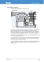
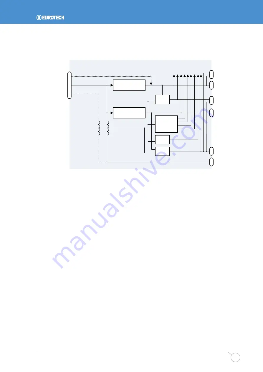
The following diagram illustrates the GCM power supply.
DC Power Input (V_IN)
Power
Management
Unit
V3.3
V5
to
on-board
circuitry
Step-Down
DC/DC Controller
Step-Down
DC/DC Controller
Graphics ClientM
5V Input
J7
J11
J8
J1
BL_VCC
Backlight Power
Power
Switch
Power
Switch
J14
Power
Switch
PWR_EN from PXA320
SYS_EN from PXA320
V5S
J22
V3.3S
J16
Backlight
Serial 2
1-Wire
GPIO
VEE Adapter
Serial 3
The GCM power supply is designed for high efficiency and low noise. It utilizes two high-
efficiency step-down DC/DC controllers to regulate the incoming DC power from
generating 3.3 V and 5 V. A multi-function, programmable power management
unit provides additional power regulation generating all other voltages required by the on-
board circuitry. For electrical specifications, see
For systems that supply regulated 5 V power, the 5 V step-down DC/DC controller can be
removed as a volume production option.
In the standard configuration, the DC power input V_IN also provides the backlight power
. As a volume production option, the GCM supports a backlight
power input on J1 that is independent of V_IN.
It is the responsibility of the designer or integrator to provide surge protection on the input
power line. This is especially important if the power supply wires will be subject to
EMI/RFI or ESD.
Содержание PXA320
Страница 62: ...www eurotech com ...

