Graphics ClientM User Manual
110120-1000A
30
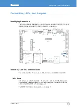
LED Indicators
The GCM has two on-board light-emitting diodes (LEDs) and two LEDs integrated with
the Ethernet socket to indicate system operation. This section describes the LED
functionalities.
D3 and D4: Software-Controllable LEDs
LED
Type
Description
D3
green
Controlled by PXA320 GPIO0
D4
red
Controlled by PXA320 GPIO1
Ethernet LEDs
, page
integrates system status LEDs with the socket. These LEDs indicate
valid Ethernet connection, speed, and bus activity.
Signal Headers
The following tables describe the electrical signals available on the connectors of the
GCM. Each section provides relevant details about the connector including part
numbers, mating connectors, signal descriptions, and references to related sections.
J1: Power Input
Board connector: 6-pin header with friction lock, 0.1-inch, Molex 22-23-2061
Mating connector: Molex 22-01-3067
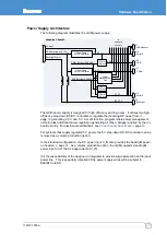
Header J1 accepts input power from an external supply. V_IN is the main power input to
the GCM. Other voltages required by the processor and peripherals are generated from
V_IN. For details about the power supply architecture including descriptions of the
volume production options, see
Pin Name
Type Description
1 5V_IN
PI
5 V power input (production option)
2 GND
P
ground
3 BL_VCC
PI
Backlight power input (production option)
4 V_IN
PI
DC power input
5 nc
6 nc
Содержание PXA320
Страница 62: ...www eurotech com ...


