System Specification
110120-1000A
49
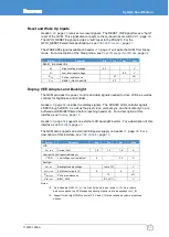
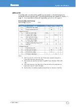
Reset and Wake Up Inputs
, page
receives two reset signals. The RESET_IN# signal forces a “hard”
reset of the GCM. This signal also connects to the on-board reset switch
The GPIO_RESET# signal provides a “soft” reset to the PXA320. For the
GPIO_RESET# electrical specifications, see
The WAKEUP# signal available on header
mode. For a description of the Sleep mode, see
, page
Symbol
Parameter
Min
Typ.
Max
Units
RESET_IN#, WAKEUP#
V
IH
High-level input voltage
2.3
V
V
IL
Low-level input voltage
0.5
V
R
PU
Pull-up resistance on
RESET_IN#, WAKEUP#
47
kΩ
V
PU
3.3
V
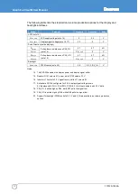
Display, VEE Adapter, and Backlight
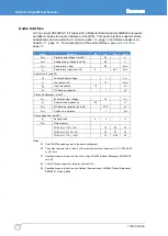
The GCM provides the power, control, and data signals needed to drive LCDs, as well as
controls for brightness and contrast.
includes the display signals. The PXA320 LCD controller signals
LDD0 through LDD15, as well as the pixel clock, vertical sync, and horizontal sync, are
buffered and EMI/RFI filtered before reaching header J6. For a description of this
interface, see
supports an external LCD backlight inverter. For a description of this
interface, see
The GCM also supports an external VEE power supply on header
. For a
description of this interface, see
Symbol
Parameter
Min
Typ.
Max
Units
LCD
I
PNL_PWR
Current limit
1.0
1.3
1.6
A
Contrast Control (passive displays)
VCON
Low-voltage contrast adjust
0
3.3
V
Backlight
V
BL_VCC
Backlight supply voltage
(note 12)
V
V
BKLT_PWM
PWM control (note 13)
0
5
V
R
BKLT_ON#
Pull-up resistance on
BKLT_ON#
12
kΩ
V
BKLT_ON#
BL_VCC
V
Notes:
12. On a standard GCM, V
BL_VCC
, is driven by the main input power V_IN. As a volume
production option, the GCM supports a backlight power that is independent of V_IN.
13. Support for backlight PWM control at 3.3 V and V_IN are available as volume production
options.
Содержание PXA320
Страница 62: ...www eurotech com ...


