Hardware specification
Issue E
25
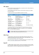
USB support
The US15W SCH contains an Enhanced Host Controller Interface (EHCI) host controller,
which supports up to eight USB 2.0 high-speed root ports (0 to 7). USB 2.0 allows data
transfers up to 480 Mb/s.
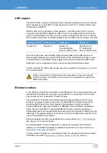
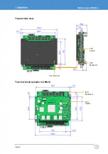
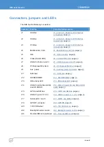
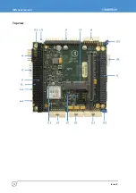
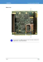
USB 2.0 ports 0-6 are available on three headers on the ISIS board. Port 6 is used in
conjunction with the SMSC USB2513i USB 2.0 hub for an additional three downstream
ports. Two downstream ports of the hub are routed to a header, the third one is routed to
the PCIe Mini Card socket. The following table shows the USB 2.0 ports routing on the ISIS:
US15W ports 0/1/4/5
US15W ports 2-3
US15W port 6
US15W port 6
Header J16
Header J7
Header J14
(Two downstream
ports of a USB 2.0 hub)
PCIe Mini Card
(3
rd
downstream
port of a USB 2.0 hub)
Common mode choke coils and ESD suppression are added to the USB data lines to
improve signal integrity and provide ESD protection. Power-distribution switches are used
to provide 500mA current-limited power supply to all eight user accessible USB2.0 ports.
USB port 2 can be configured as host or client port using the BIOS setup utility.
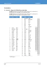
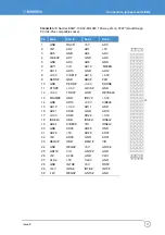
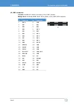
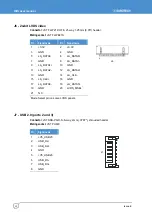
The OS boot from the USB mass storage devices is supported. See pages
for connector details.
Before connecting any USB devices that supply power to the port 2 (type-B
USB connectors), you MUST ensure that port 2 is configured as a client (via a
BIOS setup utility).
Ethernet interface
A 10/100 Ethernet interface is available on the ISIS board. This is implemented using an
Intel 82551IT Fast Ethernet Controller. The Intel 82551IT is interfaced to the PCI local
bus provided by the Tundra Tsi381 PCIe/PCI bridge.
The Intel 82551IT Fast Ethernet Controller integrates Ethernet MAC and PHY layer
functions in a single, compact component. The Intel 82551IT combines Intel’s fourth
generation MAC design, with fully integrated, physical-layer circuitry to provide a
standard IEEE 802.3 Ethernet interface for 100BASE-TX and 10BASE-T applications
(802.3, 802.3u). Intel 82551IT supports MDI/MDI-X feature, providing the ability to
automatically detect the required cable connection type and configure the MDI port to the
cable type. This feature enables auto-correction of incorrect cabling with respect to cross-
over versus straight-through cables.
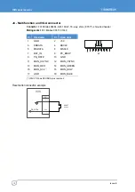
Ethernet interface and LED’s are available on an 8-way header (
, for connector details.
An external adaptor board with magnetics is required for operation of the Ethernet
interface. An ACS-9095-05 adaptor is available from Eurotech. For more details, see
, page
.
In case you wish to design your own adaptor board, the example of an Ethernet adaptor
schematic is provided in
Appendix C – Ethernet adaptor schematic
, page
.

