ISIS user manual
Issue E
28
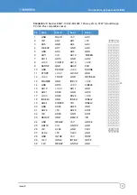
GPIO
Eight general purpose IO’s are provided via a 12-way header (J15), these are individually
configurable as inputs or outputs. GPIO1 and GPIO2 are 3.3V CMOS signals, derived
from CPU module’s CPLD. The other six GPIO’s are derived from GPIO pins of a
SuperIO device SCH3114. These six GPIO’s are 3.3V signalling, 5V tolerant signals. The
following table shows the GPIO port mapping.
Signal name
GPIO Mapping
Type
GPIO1 CPLD
GPIO1 3.3V
CMOS
GPIO2 CPLD
GPIO2 3.3V
CMOS
GPIO3
SuperIO GP61
3.3V CMOS
(*)
GPIO4
SuperIO GP54
3.3V CMOS
(*)
GPIO5
SuperIO GP56
3.3V CMOS
(*)
GPIO6
SuperIO GP57
3.3V CMOS
(*)
GPIO7
SuperIO GP50
3.3V CMOS
(*)
GPIO8
SuperIO GP51
3.3V CMOS
(*)
(*)5V tolerant
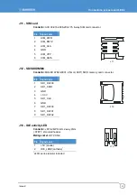
For GPIO connector details see page
SMBus
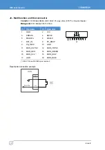
A system management bus is made available for customer use via a GPIO header (J15).
The US15W SCH provides an SMBus Rev1.0 compliant host controller. Maximum
operating frequency of SMBus as specified in
System Management Bus Specification
Rev1.0
is 100KHz.
The I²C bus and the SMBus are essentially compatible with each other. Normally
devices, both masters and slaves, are freely interchangeable between both buses. Both
buses feature addressable slaves (although specific address allocations can vary
between the two buses). The buses operate at the same speed, up to 100KHz, but the
I²C bus has both 400kHz and 2MHz versions. Obviously, complete compatibility between
both buses using all devices is ensured only below 100kHz.
For SMBus connector details see page
.

