background image

ISSUE 1/Original version/OCT 2013 
 

11 

11 

EXTENSION CABLE 

If an extension cable is required, use an approved 3-core extension cable suitable for the power input 
of this tool (see technical data).The minimum conductor size is 1.5 mm²; the maximum length is 30 
meter. When using a cable reel, always unwind the cable completely. 


ASSEMBLY AND ADJUSTMENTS 

WARNING: 

To reduce the risk of injury, turn unit off and disconnect machine from power 

source before installing and removing accessories, before adjusting or changing set- ups or 
when making repairs. Be sure the switch is in the OFF position. An accidental start-up can 
cause injury. 


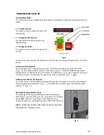
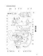
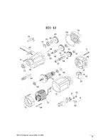
PREPARATION OF THE MACHINE (FIG.  1) 

1.


Assemble the feed handle. 

2.


Mount the drill guard. 

3.


Fit the lubrication system as necessary. 

4.


Place the machine on a clean, level and solid surface. Remove any particles that will obstruct 

full contact between the magnetic stand and the mounting surface. 

5.


Fit the safety chain (in vertical or overhead drilling applications). 


MOUNTING THE DRILL GUARD (FIG. 1) 

The guard protecting against chippings and accidental contact must always be mounted during 
operation. 

1.


Hold the guard in front of the magnet, aligning the slots in the guard with the holes in the 

magnet. 

2.


Fit the screws into the hole located in the side of the magnet. 


WARNING: 

Always use the Safety guard. 


FITTING THE LUBRICATION SYSTEM (FIG. 1) 

The lubrication system can be used for horizontal drilling applications (the drill being used vertically). 


Hold the cooling tank against the bracket on the slide and push it in its place. 


Connect the hose to the nipple on the spindle drive shaft. 

 
In order to use the lubrication system, it must be filled with a sufficient amount of cutting fluid. 

1.


Make sure the flow regulator is closed. 

2.


Unscrew the cap. 

3.


Fill the container with cutting coolant. 

4.


Screw the cap back on. 


WARNING: 

Do not use the lubrication system in vertical or overhead drilling applications. 

Instead use Euroboor cutting paste 

 
FITTING THE SAFETY CHAIN 

1.


Pass the safety chain through the opening near the handle. 

2.


Wrap the chain around the work piece. 

3.


Securely tighten the chain. 

 
WARNING: 

Always use the safety chain when using machine vertically or in up-side-down 

position. 

Содержание ECO.40/2

Страница 1: ...USER MANUAL ECO 40 2 Magnetic Drilling Machine SERIAL NO ____________ DATE OF PURCHASE __________ E U R O B O O R FOR PROFESSIONALS BY PROFESSIONALS...

Страница 2: ...ols and products to help you be more productive Before operating your new magnetic drilling machine please read all instructions rst These include the Operator s Manual and Warning Label on the unit i...

Страница 3: ...ISSUE 1 Original version OCT 2013 3 3 Fig 1...

Страница 4: ...he directives of the European Community Class of protection I Product with basic insulation and exposed touchable conductive parts additionally connected to the protective earth conductor mm Millimete...

Страница 5: ...ugs 2 Avoid body contact with grounded surfaces such as pipes radiators ranges and refrigerators There is an increased risk of electric shock if your body is grounded 3 Do not expose magnetic drilling...

Страница 6: ...switch does not turn it on or off Any tool that cannot be controlled with the switch is dangerous and must be repaired 5 Disconnect the plug from the power source before making any adjustments changi...

Страница 7: ...nto the work piece before drilling Do not perform any design assembly or construction activities on the work piece while the machine is turned on Before turning on the machine make sure the accessory...

Страница 8: ...of machine the year and month of manufacturing and identification number is engraved on the frame magnet and the motor unit Example 040 12 11 001 Model type Year of Manufacture Month of manufacture I...

Страница 9: ...igure specifications as per ISO 4871 Sound emission Measured A weighted sound power level LwA re 1 pW in decibels 103 Measuring uncertainty KwA in decibels 3 A weighted emission pressure power level m...

Страница 10: ...nforced with an additional steel plate in order to guarantee the magnetic holding power Check the machine for possible damage Before using the machine you must carefully check protective devices or sl...

Страница 11: ...L GUARD FIG 1 The guard protecting against chippings and accidental contact must always be mounted during operation 1 Hold the guard in front of the magnet aligning the slots in the guard with the hol...

Страница 12: ...l the magnet is placed on Paint or coating of the material the magnet is placed on Metal chips oil or other dirt under the magnet If the LED indicator see page 13 lights up GREEN the magnet is generat...

Страница 13: ...ll be lit red The LED indicator Fig 2 2 will be lit GREEN if generated magnetic force is sufficient When LED indicator turns RED there is not enough magnetic force and it is not safe to work To deacti...

Страница 14: ...regularly refill the holes of the spindle and continue drilling 8 Apply less pressure when the drill cuts through the material 9 Turn the arms to put the motor in highest position and turn off the mot...

Страница 15: ...he 5 self locking set screws at the left side Tighten screws in series until the gear rack moves freely in the dove tail guide but does not allow the motor to wobble Cleaning WARNING Blow dirt and dus...

Страница 16: ...machines operation must be checked to ensure that all components are working correctly Replace any defective parts immediately This prevents properly function parts from being damaged CARBON BRUSHES B...

Страница 17: ...justing all setting nuts and screws 3 Operate the slide up and down a few times to test the movement and make any further necessary adjustments Try to ensure that all the screws are exerting a uniform...

Страница 18: ...r guide not mounted straight Dirt between spindle and triangular guide Motor starts running when magnet switch is turned on Damage or defective relais in control unit Motor making a rattling sound Gea...

Страница 19: ...there is machine failure and the problem cannot be saved with one of the above solutions PROTECTING THE ENVIRONMENT Separate collection This product must not be disposed of with normal household waste...

Страница 20: ...ont plate 34 020 0206 Sensor LED cable 35 020 0006 On Off switch 36 020 0016 Fuse Holder 37 020 0017 Fuse F2A 38 020 0011 Magnet Switch 39 020 0001 Control Unit 220v 39 020 0002 Control Unit 110v 40 0...

Страница 21: ...ISSUE 1 Original version March 2013 21 21 EXPLODED VIEW of ECO 40 2...

Страница 22: ...ISSUE 1 Original version March 2013 22 22...

Страница 23: ...tic Drilling Machine Type ECO 40 2 Ratings and principal 230 240V 50 60Hz Class I Characteristics ECO 40 2 1050W N0 720 1300 min Applicable EC Directives Machinery Directive 2006 42 EC Relevant standa...

Отзывы: