background image

Euphonix Max Air Mixing Console Operation Manual


Channels and Strips

89

5.1.1

Assign Channels to Strips

Each strip can control a Main and Swap channel. One or both of the channels can be a 
Control Group Master or Multi Format Master instead of a normal channel (see Chapter 
8: 

Control Groups and Multi Format Masters

). Channels can be assigned individually 

using the strip controls or to multiple strips using the 

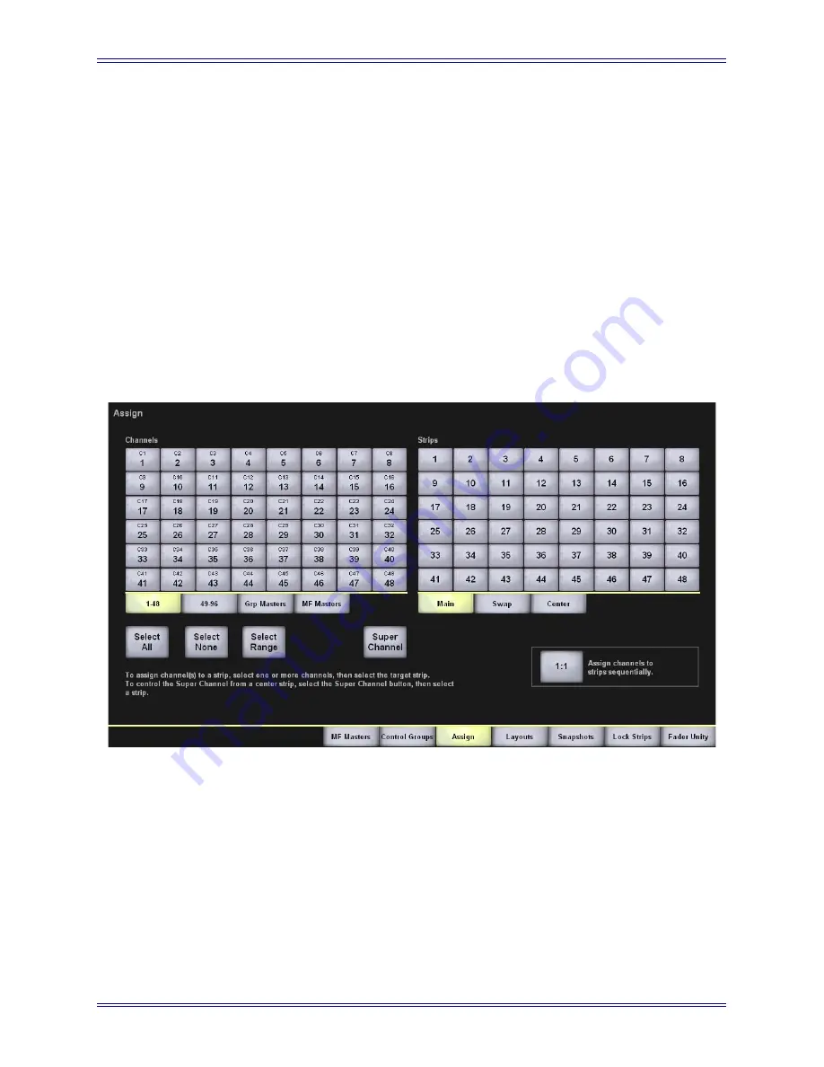
Channels - Assign View 

(see 

Channels 

on page 74) from the Touchscreen.

Channel Assign View

The 

Channels - Assign View 

on the Touchscreen is most commonly used to assign 

channels to multiple strips but can also be used for a single assignment. 

1.

Select 

Channels 

from the Main Menu buttons.

2.

Select the 

Assign 

tab.

Figure 5-2 

Channel Assign View

3.

In the 

Channel Assign View

, select the channel to assign from the Channels 

bank.

4.

Select the strip to assign the selected channel to from the 

Strips

 bank.

Содержание Max Air

Страница 1: ...evision 1 4 Software Version 1 4 Part Number 840 08718 04 Release Date September 2005 Euphonix Inc 220 Portage Ave Palo Alto California 94306 Phone 650 855 0400 Fax 650 855 0410 Web http www euphonix com e mail info euphonix com ...

Страница 2: ...ny means without written permission from Euphonix Inc Note This equipment has been tested and found to comply with the limits for a Class A digital device pursuant to Part 15 of the FCC Rules These limits are designed to provide reasonable protection against harmful interference when the equipment is operated in a commercial environment This equipment generates uses and can radiate radio frequency...

Страница 3: ... s instructions 8 Do not install near any heat sources such as radiators heat registers stoves or other apparatus including amplifiers that produce heat 9 Do not defeat the safety purpose of the polarized or grounding type plug A polarized plug has two blades with one wider than the other A grounding type plug has two blades and a third groundingprong Thewiderbladeorthethirdprongareprovidedforyour...

Страница 4: ...ly cord shall remain readily operable 19 This unit is provided with a power supply cord set suitable for 120V AC input only for U S A and Canada For other than U S A and Canada a qualified person must provide for use with this unit an appropriate approved power supply cord set which is in compliance with the end use country requirements and has a minimum cross sectional area of 1 0mm2 20 For units...

Страница 5: ... Router and Patchbay Setup 28 3 2 1 Name Ports 28 3 2 2 Assigning the Mic Preamps to Hubs 29 3 2 3 Label Destination Ports and Signals 30 3 2 4 Label Individual Signals 30 3 3 Channel to Strip Layout 31 3 3 1 Setting up Stereo Channels using MF Masters 31 3 3 2 Assign Channels to Strips 32 3 4 Busses 33 3 4 1 Create Main Sections and Audio Subgroups 33 3 4 2 Route to the Main Sections and Busses 3...

Страница 6: ...on the Current Title 52 4 2 4 Default Titles 53 4 3 Patch 54 4 3 1 Destinations and Sources 55 4 3 2 Console I O 55 4 3 3 Cabling 60 4 4 Patching Examples 63 4 4 1 Patch 12 Mics Into Channels 25 36 63 4 4 2 Main Bus Send Return 67 4 4 3 Monitor Patching 68 4 4 4 Solo Bus and Utility Patching 68 4 4 5 Talkback Signal Patching 68 4 5 Busses 69 4 6 System 69 4 6 1 Externals 69 4 6 2 Knobset 70 4 6 3 ...

Страница 7: ...ents 85 Chapter 5 Channels and Strips 87 5 1 Strips 87 5 1 1 Assign Channels to Strips 89 5 2 Channel Control Features 91 5 2 1 Channel Name 91 5 2 2 Fader 92 5 2 3 Meters 93 5 2 4 Status LEDs 93 5 2 5 Wave Key 93 5 2 6 Channel On Key 93 5 2 7 Channel Select Key 94 5 2 8 Solo Key 94 5 2 9 Copy and Paste 94 5 2 10 Rotary Knobs 94 5 2 11 Knobset Select Keys 95 5 2 12 In Out Keys 96 5 2 13 Expand 96 ...

Страница 8: ...ring Main and Group Busses 110 6 2 1 Format Selector 111 6 3 Configuring Aux Busses 114 6 3 1 Aux to Faders 114 6 3 2 Toggle On Off 115 6 3 3 Toggle Pre Post 115 6 3 4 Copy Fader to Aux 115 6 3 5 Copy Aux to Aux 116 6 3 6 Set Unity 116 6 3 7 Toggle Stereo 116 6 4 Mix Minus 117 6 5 Bus Centric Views 118 6 5 1 Goup Bus View 118 6 5 2 Aux View 118 6 5 3 Main View 120 6 6 Bus Masters 121 6 6 1 Main Se...

Страница 9: ...e 137 7 4 Oscillator 137 7 5 Solo 139 7 5 1 Solo Mode 140 7 5 2 Solo Level 140 7 5 3 Clear Solo 140 7 5 4 Solo Switch Mode 140 7 5 5 Speaker Selection 141 7 5 6 Solo Speaker Dim 141 7 5 7 Solo Safe 141 7 5 8 Backstop PFL 142 7 6 Soft Knobs 142 7 6 1 Soft Knob Setup Popup 143 7 7 Center Section Faders 144 7 8 Keypad 145 7 9 Global Functions 147 7 10 Custom Keys 148 Chapter 8 Control Groups and Mult...

Страница 10: ...hapter 10 Event System 161 10 1 Input Types 162 10 2 Output Types 163 10 3 Logical Operators 164 10 4 Event Configuration Display 165 10 5 Event List 165 10 6 Input 166 10 7 Output 167 10 8 Deleting Events 167 10 9 GPI Examples 167 10 9 1 Move a Fader to Turn Off the Floor Monitors 168 10 9 2 Move a Fader to Turn On the Floor Monitors 171 10 9 3 Move a Fader to Start a Cart Machine 173 10 9 4 Move...

Страница 11: ...Euphonix Max Air Mixing Console Operation Manual xi Index 183 ...

Страница 12: ...Euphonix Max Air Mixing Console Operation Manual xii ...

Страница 13: ...ave Current Data Popup 52 4 9 Current Title Buttons 52 4 10 Simplified MADI routing diagram 54 4 11 Sources and Destinations with respect to Max Air 55 4 12 Console I O A and B Inputs View 56 4 13 Sources and Destinations Selected 57 4 14 Patch Complete 58 4 15 Source input naming 59 4 16 Sources patched to channels 59 4 17 Cabling MADI Out Port 61 4 18 Cabling MADI In Port 62 4 19 Sources View wi...

Страница 14: ...4 40 Meters Screen Popup with Meters Display 83 4 41 Meters Fader Popup 84 4 42 Meters Setup View 85 5 1 Console Strip and Bus display with block diagrams for Main and Swap channels 88 5 2 Channel Assign View 89 5 3 Channel Selector 91 5 4 Main and Swap Channel displays 91 5 5 Strip Fader 92 5 6 Rotary Knob Controls 95 5 7 Strip Function Switches 95 5 8 Mono Input knobsets 96 5 9 Stereo Input Knob...

Страница 15: ...ntrols 124 7 3 Super Channel Selected Channel Pan Filters and Input 125 7 4 Super Channel EQ Insert 127 7 5 Super Channel Dynamics 128 7 6 Monitoring Matrix 129 7 7 CM404 Monitor Controls 130 7 8 Monitors Setup Popup 130 7 9 Control Room Setup CR Source 132 7 10 Control Room Setup CR Output 132 7 11 CM404 Talkback Slate 134 7 12 Talkback Slate Setup Popup 135 7 13 Listenback Setup Popup 136 7 14 S...

Страница 16: ...5 Store Snapshot Channel View 159 10 1 Event View 165 10 2 Add Input Event Popup 166 10 3 Add Output Event Popup 167 10 4 Monitor Off Inputs Set 169 10 5 Action Popup 170 10 6 Monitor Off Outputs Set 170 10 7 Monitor On Inputs Set 172 10 8 Monitor On Outputs 173 10 9 Machine Popup 174 10 10 Start Cart Inputs and Outputs Set 175 10 11 Stop Cart Inputs and Outputs Set 176 10 12 Camera Channel On Inp...

Страница 17: ... the fastest way to begin us ing Max Air s basic features Since this chapter depends on using the Touch screen read page 45 48 to acquire introductory knowledge before beginning Chapter 4 Touchscreen Since Max Air uses Touchscreen software to imple ment its ground breaking user interface it is important to get acquainted with this new technology We recommend reading this chapter in its entirety Ch...

Страница 18: ...it to hover over the heading and turn into a fin ger Then click to locate to that subject and page All cross references are active links Allow the hand cursor to hover over the reference turn into a finger and click to follow the reference Use the left and right arrow keys on the top bar to go back and forth between views This is a great way to follow a cross reference and return to the page from ...

Страница 19: ...ed to accommodate 672 sources suitable for large commercial installations Digital and analog I O units connect all of the devices in the studio via MADI All audio signals are converted to and from the MADI format through analog and digital convert ers The basic Max Air system includes four MADI Inputs and three Outputs to connect I O devices Additional MADI ports can be added by expanding the syst...

Страница 20: ...igure 1 1 Typical Max Air Hardware Configuration MC524 Monitor Interface MA703 MADI to Analog MIDI I F GPI O MA703 MADI to Analog AM713 Analog to MADI ML530 Analog Mic Line AM713 Analog to MADI Talk Listen Mics Speakers FC726 Digital FC726 Digital Ethernet Control MADI Analog Audio Digital Audio 24 24 24 Typical Max Air Configuration 96 Full Channel Signal Paths Inputs 112 Digital 24 Mic 24 Line 1...

Страница 21: ... fader Channels perform all of the signal processing EQ dynamics routing gain etc The control surface connects to the DF64 via ethernet and the EuCon Hub audio does not pass through the control surface The Max Air control surface consists of a CM404 center section with Touchscreen 1 Super Channel 4 Soft Knobs 2 and 8 center section faders 3 The channel strips 5 of which there can be a total of 48 ...

Страница 22: ...ormat Masters Chapter 8 Control Groups and Multi Format Masters 1 3 Additional Hardware Components The following hardware devices are also used in the Max Air system System Computer SC261 Runs the Max Air Touchscreen software applica tion all file management and system setup is done from this computer See Chapter 4 Touchscreen Interface Pilot Computer PC253i Supervises control functions for the an...

Страница 23: ... can select all of the modules by holding down the Ctrl key on the keyboard and selecting each of them When all modules are selected touch Save selected as default and confirm the se lection by clicking OK 5 Click Continue to finish booting Since Max Air has been designed for live on air applications the system is designed to tolerate variations in the startup sequence The system will boot properl...

Страница 24: ...Euphonix Max Air Mixing Console Operation Manual Introduction 24 ...

Страница 25: ...SB devices can be used to save titles and configuration data Router Mnemonics Max Air now provides support for displaying router mnemonics on channels which are fed from a facility router see page 58 Preferences The Preferences tab in the System View has several new items see page 72 Aux Bus Configuration Aux bus parameters can now be quickly set for multiple Aux busses unity pre post fader on off...

Страница 26: ...Euphonix Max Air Mixing Console Operation Manual New Features in Version 1 4 26 ...

Страница 27: ...te a new Project by touching the New button A Project is a folder that contains titles for a show location or operator 6 Name the project using the keyboard popup and press Enter 7 Select Titles tab 8 Create a new Title by pressing the New button A Title can contain all settings for a show each engineer can have their own Title different Titles can be used for different versions of the same show 9...

Страница 28: ... this is done these settings can be saved as the Default Title and used for newly created Titles Commonly used patches can be added to the Default Title setup in the same way a traditional patchbay can be normalled 3 2 1 Name Ports 1 Select Patch from the Main Menu buttons on the right of the Touchscreen 2 Select the Sources tab in the Patch view We will rename ports to match the connections of th...

Страница 29: ...the corresponding input channel knobset 1 In the Patch view select the Cabling tab 2 Select MADI Out Ports from the list on the left These refer to the MADI output of external mic preamps each with 24 chan nels In our example we only have one 3 Select the green MADI Out box next to Mic1 Port It is displayed in the Sources list on the right 4 Select MADI In Ports from the list on the left 5 Select ...

Страница 30: ...el Individual Signals From the Patch view 1 Select the Sources tab 2 Select Mic Line 1 from the list on the left 3 Select Rename Port and enter Mic 1 24 using the keyboard popup This enters meaningful names into each of the 24 mic input name slots 4 Each mic can now be individually named Touch the first beige box in the Name column that shows Mic 1 24 1 Use the keyboard popup to rename it Mic 1 Yo...

Страница 31: ...6 are stereo channels A Multi Format Master is a single control strip that can control more than one channel It can be setup as a stereo master controlling 2 channels with a balance control and Left Right to Mono selection The MF Master Strip controls both channels adjusting the EQ on a Stereo MF Master adjusts the EQ s of the two channels assigned to it Setup Stereo Multi Format Masters for Chann...

Страница 32: ...ls menu button on the right side of the screen 2 Select the Assign tab 3 Select the Select Range button To assign Channels to Strips 4 Select the 1 48 tab beneath the left bank of buttons called Channels Select channels 1 16 from the bank by pressing channel 1 button and then 16 All 16 channels are selected 5 Select the Main tab beneath the right bank of buttons called Strips Touch the Strip 1 but...

Страница 33: ...following formats mono M mono LR M M stereo L R LCRS L C R S 5 1 L C R SL SR B 6 1 L C R SL SR SC B 7 1 L LC C RC R SL SC SR B Main sections can be set to different formats i e A stereo B mono C 5 1 These are the Main output groups of the console which can be monitored directly from the control room monitor section They can also be used as audio subgroups and clean feeds Setup Subgroups and Main P...

Страница 34: ...nnels from the Main Menu buttons 2 Select the MF Masters tab 3 Since MF Masters 1 32 are already used select the Masters 33 40 tab beneath the bank of channel buttons 4 Page through the channels to show Page 7 of 7 This brings up bonus channels 97 106 These extra channels are very useful as processing channels for group masters Max Air only allows the first 96 chan nels to be assigned to Strips so...

Страница 35: ...r MF Masters to the first four faders in the center Their designations light up on the surface to show they have been assigned It is also possible to use two channels 105 and 106 controlled by another MF Master to act as main signal processing stereo channel for the program bus E if required These would be set up as above fed from Main section E The main program output would be the channel output ...

Страница 36: ... is routed to Main section A Do this for the first 16 Strips 4 Press any Strip s Swap button and repeat steps 2 and 3 so that the backup mics plugged into channels 17 32 are also routed to Main section A Route Subgroups A D to the E Main Section Program Output 1 Press the blue Wave key next to the first center section fader which controls MF Master SubA This brings the MF Master s parameters into ...

Страница 37: ...sing the 24 Group Busses Max Air includes 24 Group busses These are very useful for additional clean feeds or extra stereo outputs As an example we could use Groups 1 and 2 as a stereo foldback output 1 Select Busses from the Main Menu and the Group tab 2 Check that 1 and 2 are set to stereo If not select the stereo format from the For mat Selector select busses 1 and 2 and press the Set Format bu...

Страница 38: ...e from a wide variety of signals to display here Since there are meters set up on every channel it is probably best to select the screen meter area to display Subgroups Aux Masters Solo and Program In this example we will place the meters for these busses on the screen 1 Select Meters from the Main Menu 2 Select the Screen tab 3 Select the left most meter bank area selected bank shows a yellow out...

Страница 39: ...can put channel meters along the top of the Touchscreen There are 48 meter spac es available along the top row not including the right corner section Note that there are two options with the Channels and Strips buttons channels are the actual logical chan nels Strips are the physical position of the Strips on the console If you set the meters to show channels these will not necessarily match what ...

Страница 40: ...at indicate the channel functions 4 Select the bottom box on the left It highlights yellow to show it is selected 5 Select the Input function in the middle column The grid on the right shows all input functions of the channel strip 6 Select the A input Gain situated in the bottom left of the bank of buttons There are two inputs per channel each with Impedance 48 V phantom High Pass Filter Mic Gain...

Страница 41: ...l sources i e Off Air Stereo Dolby E Decoded 5 1 CD player etc 3 7 1 Patching External Devices into the External Inputs Decide the sources to be patched into external inputs For example the first 24 digital sources coming into the console that we labeled Digital In 2 are external sources 1 Select Patch from the Main Menu 2 Select the Sources tab 3 Select the fourth gray button which should now be ...

Страница 42: ...on the far left and name the device Off Air 7 Repeat the steps above for all externals The system allows any combination of formats For example a 5 1 Dolby E monitor set of six inputs could be assigned as a 5 1 format to device button 2 3 8 Monitors Setting up the monitors is the final step to getting sound to the speakers Note that only certain monitor outputs can handle surround outputs Figure 3...

Страница 43: ...ional monitoring includ ing green room feeds floor foldback etc Setup is simple press the Setup button at the top right of the Super Channel section to bring up the source options for these monitors 3 9 Save a Default Title Once you have completed this setup process you should save this Title 1 Touch the File menu button and select the Title tab 2 Touch the Save button in the Current Title box to ...

Страница 44: ...Euphonix Max Air Mixing Console Operation Manual Quickstart to Common Tasks 44 ...

Страница 45: ...ivated by touching a menu button or tab There is no Close button to a View Change Views by selecting another View The term Popup is used for a window of topical information that is opened by touching a button and closed by touching a Close button A Popup is similar to a dialog box in other systems When a keyboard popup is presented to name something Figure 4 1 either touch the letters onscreen or ...

Страница 46: ...d name Control Groups assign channels to Strips configure Layouts and Snapshots lock Strips and set faders to unity gain Busses configure and assign group main and aux busses Super Channel shows all settings of the Super Channel Events GPI O event configuration Meters configure meters and meter presets System configure external monitor inputs configure custom knobset view Mixer Model and set Prefe...

Страница 47: ...tion Viewer 6 and a display of the current Title and Time of Day Clock 4 Meters 1 The area at the top and upper right of the display is used for level meters View Area 2 The majority of the screen area between the meters and the per manent display is used for context sensitive Views Popups These are like dialog boxes used for a specific task i e oscillator pa rameters keyboard etc that remain on s...

Страница 48: ...4 4 Touchscreen Navigation Views are selected from the Main Menu buttons on the right side of the screen 1 Sev eral views have multiple sub views accessed by tabs 2 Within a view Ranges Tabs 3 select additional values and Screen Buttons 4 control various functions 3 4 2 1 ...

Страница 49: ...e operations are almost identical to those in Windows or the Macintosh Figure 4 5 Drives View Select the Drive on which to begin a new Project or open an existing Project The Drive name highlights but the Open button is dim because it is not necessary to open the drive just select the Projects tab to find the project to open on that Drive 4 2 1 Projects Select the Projects tab to view the Projects...

Страница 50: ... a Project name The name highlights and there is no need to touch the Open but ton for the Project since it is dim you cannot Just touch the Titles tab to see the Titles within the selected Project see Titles on page 51 to learn how to open a Title Rename Copy Paste or Delete Project The Rename Copy Paste and Delete buttons are located in the Selection area on the right side of the Projects View T...

Страница 51: ...selected Project s name is Test the copied Project is Copy of Test Touch the Rename button to rename the selected Project in the keyboard pop up that appears Touch Enter to complete the process or Cancel to leave the name unchanged Touch the Delete button to delete the selected Project The Project is deleted and cannot be pasted 4 2 2 Titles A Project must exist before selecting opening or creatin...

Страница 52: ...ears Figure 4 8 Save Current Data Popup Yes Saves the settings from the current title into the new title No Uses settings for Default Title to reset console See page 53 to see how to change the default settings Open Existing Title Select the Title name and touch the Open button in the Selection area 4 2 3 Operations on the Current Title Figure 4 9 Current Title Buttons The three buttons in the Cur...

Страница 53: ...way to browse the File system without losing your place Edit Notes Touch the Edit Notes button to enter any information about the Title The notes are dis played below Title names in the Title View 4 2 4 Default Titles The settings stored in the Default Title are automatically included with each new Title Each Mixer Model has a Default Title file The following settings are contained in the Default ...

Страница 54: ...hannel inputs and outputs The Euphonix AM713 analog to MADI and MA703 MADI to analog pro vide 24 fixed gain channel inputs and outputs The Euphonix ML530 provides 24 remote variable gain analog mic line preamps that can be controlled from the Strip The Euphonix FC727 and FC726 provide 56 channels of digital format conversion Some equipment such as the Euphonix R 1 the Sony 3348HR recorder and some...

Страница 55: ...i e signals sent to the MADI to digital converters VTR inputs Figure 4 11 Sources and Destinations with respect to Max Air If you have purchased an SH612 Studio Hub there are up to 12 MADI device input ports and 11 MADI output ports on the console each carrying up to 56 channels If you do not have a Studio Hub there are four MADI input ports and three MADI Output ports available 4 3 2 Console I O ...

Страница 56: ...nctions Patch Selected Patches selected patchpoints 3 in Figure 4 12 An error message appears if the sources are not properly matched to the desti nations There must be an equal number of sources and destinations or one source to multiple destinations Unpatch Selected Unpatches selected patchpoints Select None Deselects all patchpoints View Log Shows a log of failed patches 1 2 3 4 5 ...

Страница 57: ... appear in the Sources column of the Selected Sources and Destinations area next to their counterparts in the Destinations column 3 in in Figure 4 13 Figure 4 13 Sources and Destinations Selected 3 Touch the Patch Selected button 4 in Figure 4 13 to make the Patch Note in Figure 4 14 that the Selected Sources and Destinations area is cleared 1 in Figure 4 14 and the A Input names appear next to th...

Страница 58: ...ature in Preferences NOTE This function will only work as described if the console has been integrated with the router system as described in the Max Air Installation Guide To enable importing of names to channels enter X as the Source Input name on the Touchscreen indicates that the input is a router input or output X indicates the number associated with that router destination console input 1 2 ...

Страница 59: ...al Touchscreen 59 Figure 4 15 Source input naming The channel displays on the console surface are updated as the names associated with the sources patched to the channels are changed and sent from the router Figure 4 16 Sources patched to channels ...

Страница 60: ...nalog outputs are connected to an AM713 Analog to MADI converter which then con nects to one of the MADI inputs The patch system must be informed which MADI input each ML530 connects to so their input controls appear on the corresponding input channel knobset Note how each Mic Line Interface is connected In the example that follows the MADI output from the Analog to MADI converters of two ML530 Mi...

Страница 61: ...c1 and Mic2 in the MADI Out column 3 in Figure 4 17 The cells highlight green and the names appear in the Sources column of the Selected Sources and Destinations area 4 in Figure 4 17 Figure 4 17 Cabling MADI Out Port 4 Select the MADI In Ports sub category 1 in Figure 4 18 5 Touch and drag through the cells to the right of the two Hub1 inputs Hub1 1 and Hub1 2 2 in Figure 4 18 The cells highlight...

Страница 62: ...tem now knows how the two mic line interfaces are connected so the proper input controls appear at the top of the channels they are connected to Because Hub1 1 and Hub1 2 have been designated as MADI connections to the Mic Line interfaces touching Hub1 1 and Hub1 2 in Sources shows Device Patch in the first 24 cells and will not allow selection unless they are unpatched 1 2 3 4 ...

Страница 63: ...gure 4 19 This displays all inputs from the first Mic Line Interface in the Name column The Mic Line Interface is connected as part of the initial studio setup 3 Select Mic1 1 Mic1 12 from the Mic Line column by touching and dragging through the cells 3 in Figure 4 19 These entries are highlighted in green in the Sources column of the Selected Sources and Destinations area 4 in Figure 4 19 If ther...

Страница 64: ...b 1 in Figure 4 20 then select the A and B Inputs sub category 2 5 Select the 17 32 tab to display those channels 6 Select channels 25 32 by touching and dragging through the A Input column next to C25 C32 7 Select the 33 48 tab to display those channels 8 Select channels 33 36 by touching and dragging through the A Input column next to C33 C36 3 in Figure 4 20 The entries are highlighted in green...

Страница 65: ... the Patch Selected button 5 in Figure 4 20 to make the connection The sources and destinations appear in the A Input and Name columns re spectively 1 in Figure 4 21 The sources and destinations are cleared from the Selected Sources and Destinations area 2 in Figure 4 21 Figure 4 21 Mic Patch Complete 1 2 3 4 5 1 2 ...

Страница 66: ...d 4 Select the Console I O category 5 Select the A and B Inputs sub category 6 Touch and drag through the first 24 cells in the A Input column These cells are highlighted and their names appear in the Destinations column in the Selected Sources and Destinations area on the right 7 Touch the Patch Selected button to make the connection The sources and destinations appear in the A Input and Name col...

Страница 67: ...e Console I O category and then select the Main Busses sub category Each Main bus has a send and return Figure 4 24 shows the first six sends a 5 1 channel Main section routed to channels 41 46 A inputs The insert is switched in out from the Bus Masters Config Page see Bus Inserts on page 122 Figure 4 24 Main Bus Send and Return 1 2 ...

Страница 68: ...he insert point into all mon itor signal paths 4 4 4 Solo Bus and Utility Patching The Solo Busses sub category in Console I O allows custom patching into the stereo Solo Bus The Utility Sources sub category includes the Oscillator output The Utility Destina tions sub category includes the Slate In which must be patched to the Talkback mic feed from the Monitor Interface 4 4 5 Talkback Signal Patc...

Страница 69: ...es See Chapter 6 Busses 4 6 System The System View has five tabs Externals Knobset Mixer Model Preferences and About 4 6 1 Externals Select the Externals tab from the System View to configure the Externals in the same way as Main and Group busses Figure 4 25 Externals View ...

Страница 70: ...4 26 Knobset View 1 Select the page 1 in Figure 4 26 and knob position 2 for the function param eter from the Custom Knobset area on the left 2 Select a Function from the center of the View 3 3 Select the parameter from the Function Parameters section on the right 4 4 Repeat for each of the four knob positions and pages The Fader button can be used to put the Swap channel s fader on a knob This ca...

Страница 71: ... View Max Air currently supports two Mixer Models one with and one without a Studio Hub To activate a different Mixer Model touch the Max Air Models button on the left of Figure 4 27 The two Mixer Models are displayed in the area below Select the desired Mixer Model and touch the Activate button Figure 4 27 Mixer Model View ...

Страница 72: ...values Show value when touched name otherwise Displays the value of the knob parameter when touched and reverts to the name afterwards Always show name Displays the parameter name even when touched Always show value Displays the parameter value even when touched Fader Text Display Mode The Fader Text Display Mode buttons intercancel between the same three values de scribed above but the setting ap...

Страница 73: ...erface 2 From the Main Menu press System 3 Set the Clock Source to External 4 Select the desired display format from Clock Display Format Clock Display Format Allows the clock to be displayed in three formats 12 24 hour HH MM SS FF Misc Show Router Names This enables the router mnemonics feature see page 58 Group Bus as Mix Minus Activating this button inverts the group bus assignment in dicators ...

Страница 74: ...of the screen Figure 4 29 Channels Tabs 4 7 1 Multi Format Masters See Chapter 8 Control Groups and Multi Format Masters 4 7 2 Control Groups See Chapter 8 Control Groups and Multi Format Masters 4 7 3 Assign Select the Assign tab from the Channels View to assign channels to strips in the Assign View Figure 4 30 shows the Assign View with channels 1 8 selected Figure 4 30 Assign View ...

Страница 75: ...Channel from the Center Strip select the Super Channel button and select a strip Touch the 1 1 button to assign channels 1 48 to Strips 1 48 Main Select Range Use the Select Range button at the bottom right of the Assign View to select a channel then select a higher or lower numbered channel to select all channels in between The range can include channels in another tab i e C25 C55 C15 M25 The ran...

Страница 76: ...idually accessed See Spill on page 153 for details To create a Spill area 1 From the Main Menu press the Channels button 2 Select the Spill tab 3 Select the strips to include in the Spill area Figure 4 31 Spill Area function 4 7 6 Lock Strips Select the Lock Strips tab to display the Lock Strips View Figure 4 32 which pro vides the ability to prevent strips from being affected by Layout recall ...

Страница 77: ...s both Main and Swap Use the Select All Select None and Select Range buttons see page 75 to assist your selection There is no Close button just select an other view and this information is retained 4 7 7 Fader Unity Select the Fader Unity tab to display the Fader Unity popup Figure 4 33 which al lows setting the fader on designated strips and channels to 0 dB Figure 4 33 Fader Unity popup ...

Страница 78: ...to select the strip channel type Use the Select All Select None and Select Range but tons see page 75 to assist your selection Touch the Set Unity button to set the selected faders to 0 dB 4 8 Status Touch the Status Main Menu button to display the Status View When a system error occurs and the user is not in the Status View the Status Main Menu button turns red alerting the user to inspect the St...

Страница 79: ...Channel Figure 4 35 Super Channel View Assign a channel to the Super Channel by any of the following methods Press the Wave key on any Strip Enter the channel number on the numeric keypad on the Center Section See Keypad on page 145 Press the arrow keys in the Selected Channel area of the Super Channel on the console surface to select a channel Press the Setup button in the Selected Channel area o...

Страница 80: ...per Channel Select the Channel View button to assign any channel Group Master or Multi Format Master to the Super Channel by selecting the 1 48 49 96 Grp Masters or MF Masters tabs respectively 4 9 1 Process Order The process order for the channel assigned to the Super Channel can be changed by touching the Setup button on the left of the Touchscreen Figure 4 37 Process Order Popup ...

Страница 81: ...ourth Positions button it becomes the fourth process with Ins sliding one position to the right 4 9 2 Main and Group Bus Routing The Main and Group bus routing for the channel assigned to the Super Channel can be set by touching the Setup button on the upper left of the Super Channel View Figure 4 35 Figure 4 38 Channel Routing Popup Touch the Group Busses buttons to assign the channel to those bu...

Страница 82: ...tabs discussed below the configuration can be captured as a preset named and recalled for later use Figure 4 39 Meters Presets Popup Select a numbered preset button Touch the Store button to store the current meter con figuration to that preset Touch the Name button to assign an 8 character name in the keyboard popup To recall a preset touch the desired preset button and then touch the Recall butt...

Страница 83: ...on section 1 in Figure 4 40 lists the types of meters that can be displayed The Channels function 2 is shown in Figure 4 40 which is representative of the inter face for the other functions The Strips Channels Group Masters and MF Masters functions have a Show Gain Reduction button 3 which when activated displays the amount of gain reduction applied by the compressor Select a meter bank on the top...

Страница 84: ...st your selection page 75 Touch a Meter Display button to configure the selected Strip Fader The Main or Swap channel is displayed depending upon the state of the strip s Swap button When the Swap button is pressed to change from the Main to Swap channel the meter follows this change Fader with Gain Reduction The Main or Swap channel is displayed with gain reduction Main and Swap The Main and Swap...

Страница 85: ...ters Setup View which determines the meter ballistics for all currently displayed meters Select Peak or Average to display the de sired meter ballistics NOTE This setting although not saved with the preset is saved between system shutdown and restart Figure 4 42 Meters Setup View 4 11 Events See Chapter 10 Event System ...

Страница 86: ...Euphonix Max Air Mixing Console Operation Manual Touchscreen 86 ...

Страница 87: ...to that channel from two locations Channel to strip assignments can be named stored and recalled as Layouts see Layouts on page 155 Channel settings EQ dynamics routing gain etc can be named stored and recalled as Snapshots see Snapshots on page 157 Max Air channels are mono unless they are defined as stereo LCRS 5 1 6 1 7 1 formats through Multi Format Masters see Chapter 8 Control Groups and Mul...

Страница 88: ... 32 33 33 34 34 35 35 36 36 37 37 38 38 39 39 40 40 41 41 42 42 43 43 44 44 45 45 46 46 47 47 48 48 Swap Solo On EQ Function 4 of 7 Function 5 of 7 Function 6 of 7 Function 7 of 7 Pre Fader Output Solo PFL AFL Aux Sends Group Busses Matrix Clean Feeds Main Busses Program Sub Groups System Buses Channel Output Mix Minus Output Fader Mute Any Order Insert Function 3 of 7 Function 2 of 7 Delay DYN Pa...

Страница 89: ...lly using the strip controls or to multiple strips using the Channels Assign View see Channels on page 74 from the Touchscreen Channel Assign View The Channels Assign View on the Touchscreen is most commonly used to assign channels to multiple strips but can also be used for a single assignment 1 Select Channels from the Main Menu buttons 2 Select the Assign tab Figure 5 2 Channel Assign View 3 In...

Страница 90: ...n Channels Sequentially Select 1 1 to automatically assign channels starting with channel 1 to the main layer of all strips starting at strip 1 Super Channel To assign a strip to follow the Super Channel 1 Select Super Channel below the channels bank 2 Select a strip from the strips bank Any channel assigned to the Super Channel is now controlled by that strip Using the Strip to Assign Individual ...

Страница 91: ...annel Control Features 5 2 1 Channel Name The Main and Swap channels are designated by a number C by default or by an eight character name assigned in the Patch View see Patch on page 54 The Main channel is below the Swap channel Press the Swap key to key between the Swap and Main channels The strip functions control only the active channel Figure 5 4 Main and Swap Channel displays MainChannel Swa...

Страница 92: ...position Fader Select Key The fader Select key is used to select the fader for copy page 94 and clear operations page 147 12 36 6 0 6 12 18 24 30 clip 0 6 12 24 48 48 72 3 6 12 24 Select Select Select Cha n 48V ST Mix Lo ck M S L Solo On Meters Gain reduction LEDs Touch sensitive fader Status LEDs Channel On key Solo key Wave Key Fader select Channel On Chan Select key Select key key Status LEDs ...

Страница 93: ...ing explanations pertain to the LED being illuminated 48 V phantom power is on for the mic preamp of the active channel Phase phase is inverted for the active channel Lock strip is locked page 76 ST active channel is stereo page 151 Mix Minus mix minus key is pressed page 108 Fader Touch Sensor LED fader is being touched M active channel is Group or Multi Format Master Chapter 8 Control Groups and...

Страница 94: ...y pressing their Knobset Select keys 3 Press and hold the Wave key down and press the Copy key to stop it from flashing and exit the mode To paste the settings to a new channel 1 Select the Swap or Main channel within the desired strip 2 Press and hold the Wave key down and press the Paste key on the new channel The buffered information is pasted to the channel on the new strip 5 2 10 Rotary Knobs...

Страница 95: ... s four rotary knobs by the Knobset Select keys above the knobs If the function has more than four parameters the WX keys below the first knob page backward and forward to display the additional settings The Ins Inp Dyn EQ and Filt keys double as process in out keys when the In Out key is selected Figure 5 7 Strip Function Switches On Select Bus Mix Group Main Pan Aux Filt EQ Dyn Ins Inp Knobset S...

Страница 96: ...he Ins Inp Knobset Select key to display the input controls on the knobs Press the X key to display the B input page with the same controls as the A input Each channel has an A and B input The Inpt knob bottom can feed A B or A B to the channel These two inputs can be used in many ways but a common application is one Mic and one Line Another common use is for backup mic inputs Channel 1A is from t...

Страница 97: ...s knob adjusts the digital trim 15 dB Aphs Press the lower key to the left of the knob to toggle the phase The key lights to indicate phase reversal There is also a phase reversal light next to the fader Dly Press the lower key to the left of the knob to enable the delay The key lights to indicate the delay is active Rotate the knob to adjust the delay in the range 0 2160 samples Inpt This knob se...

Страница 98: ...e HiZ 48v HPF Gain On On On On Select Select Select Select Copy Paste Trim Bal Dly Inpt On On On On Select Select Select Select Copy Paste Swap Aphs Bphs Page 1 Page 2 Page 3 Input Select Delay Mic Gain A Input Phase B Input Phase B Input A Input On Off On Off On Off Right to Mono Left to Mono On Off On Off On Off On Off Input Trim Balance On On On On Select Select Select Select Copy Paste cDpt cG...

Страница 99: ...aximum gain reduction in the expander SC sidechain source channel key link xRat ratio infinity 1 gate xThr Expander threshold dB xRel Expander release time xAtk Expander attack time cRel Compressor release time cAtk Compressor attack time 5 3 3 EQ Each channel has a four band parametric equalizer Press the EQ Knobset Select key to display the EQ controls on the knobs Figure 5 11 EQ knobsets On On ...

Страница 100: ...mber corresponds to narrower bandwidth At a given Q setting changing the gain affects the bandwidth slightly the bandwidth decreases as gain increases This creates a wider area of boost cut at low gain and allows a more natural sound as gain changes without altering the Q At full boost or cut the bandwidth is measured 3 dB down from the center frequency Since Q and Frequency share the same knob bo...

Страница 101: ...hes each filter in out Filter Q F1Q F2Q The band pass and notch filters have a variable Q from 0 2 to 12 This function has no effect on high or low pass filter types Filter Frequency F1fr F2fr The frequency range is 20 5 Hz to 21 kHz Listen To help find problematic frequencies the Notch filter can be put into a band pass mode by pressing the Listen key to the lower left of the Filter Frequency kno...

Страница 102: ...om Level Boom The level to only the Boom channel For example in 5 1 channel format the Boom level applies to only the Sub Pan Rear PanR Same as PanF for rear speakers Surround Pan Srnd Controls the front to surround levels without changing the in dividual front or surround pan settings Pan Front PanF Controls the front channel levels only i e in 5 1 channel format pan applies to LCR This is the fa...

Страница 103: ...o signal is present in the left or right channel etc As the Divergence is de creased the degree of panning is decreased The signal level increases in channels that previously had no signal and the difference in signal level between channels decreases The purpose of Divergence is to allow someone listening on the extreme left or right to hear a sound panned fully to the other side For example at 50...

Страница 104: ...s the first four Aux busses with 1 2 set to a stereo pair and others to mono Press the X key to display additional busses Stereo busses use two knobs The Pan knob top adjusts the stereo Pan and its lower left key switches Pan in out The Gain knob labeled with the send numbers adjusts the overall Gain for both sends and its lower left key switches the pair in out The upper left key switches the sen...

Страница 105: ...rocess Order on page 80 for information on changing the processor order 5 4 2 Insert Point Each channel has an insert point with a send and return that can be patched within the Patch View The insert point can be anywhere among the six other processors Delay Metering EQ Filters Dynamics and Fader The insert point can be switched in out using the Ins Inp Knobset Select key when In Out is selected E...

Страница 106: ...he keys light to indicate this channel is assigned to that group bus Group busses can be assigned in pairs by pushing the knob Hold the Group key and press the Pan key to engage the Pan for the group busses The Pan key lights dimly in other modes to show that Pan is active in main and or group bus routing The Group key also lights dimly in other modes to show that the channel is assigned to one or...

Страница 107: ...e X key to display addi tional Main Section Routing pages if there are more than four The lower key to the left of each knob turns that section on off Pressing the knob displays the individual busses of that main section on the knobs The lower key to the left of the knob toggles that bus on off Hold the Main key and press the Pan key to key Pan in out for the Main sections The Pan key lights dimly...

Страница 108: ...ally connect the MC524 s Talkback 1 output to a spare A D input on an AM713 3 In the Patch view patch the A D Source into the Utility Destinations Slate TB_In Holding down the Talk key located to the left of the Swap key above the fader switch es the talkback mic into the channel s mix minus output Figure 5 18 Mix Minus Processing The Pre Post Selector is set from the Mix Minus Bus Configuration v...

Страница 109: ...ion al mix minus bus routing and sub groups Group busses can be configured to any for mat but are usually set to odd even stereo pairs With Pan switched out they act as mono busses Aux Busses Aux busses are used for effects foldback and complex mix minus feeds that require a separate level control for each channel see page 108 for conventional mix minus bus routing Aux busses can be configured as ...

Страница 110: ...sses respectively Figure 6 1 shows the Main busses Fig ure 6 2 shows Group busses Group and Main busses differ in three ways There are 24 Main busses but only one set of Group busses Main busses have associated recorder playback returns Main busses can be named but Group busses cannot Figure 6 1 Main Bus View NOTE There are 16 Main Sections A H J U The letters I L M and N were not used to avoid co...

Страница 111: ...one another Touch the cell to the right of the letter to name the section The Main sections are the main mix outputs of the console A Main section consists of one or more Main busses There are 24 busses available 6 2 1 Format Selector To set the pan format for a Main section 1 Select the busses to configure 2 Touch the right arrow in the Format Selector to scroll through the formats Touch the left...

Страница 112: ...le if two bus cells are selected and the LCRS format is selected the two lower numbered cell receives LCRS L and the higher numbered cell receives LCRS C It is also possible to set busses to a format and then reformat some of those busses to None For example if four busses receive the LCRS format three could be selected and set to None leaving just LCRS S If there are more selected bus cells than ...

Страница 113: ... L C R Sl Sr B Any format can be re ordered but the following example sets a 5 1 channel mix to an arbi trary order 1 Select a Main bus 2 Select the 5 1 format from the Format Selector 3 Touch all channels except the first channel in your new order in the Format Se lector to de select them 4 Touch the Set Format button to set that channel to the selected bus 5 Repeat steps 1 4 for each Main bus to...

Страница 114: ... depends on the Mixer Model 6 3 1 Aux to Faders It is now possible to control a selected Aux bus from the faders Aux busses now have 12 dB of gain to match the range of the channel fader 1 Touch the Aux to Faders button The button illuminates 2 Touch the desired Aux bus to map onto the faders The button illuminates 3 When finished select another Aux or select a different Aux function This stays en...

Страница 115: ...ggled pre post fader from this View 1 Touch the Toggle Pre Post button The button illuminates 2 Touch the desired Aux busses to toggle 3 When finished select a different Aux function This effects only those channels on the surface 6 3 4 Copy Fader to Aux The CM416 fader levels and pan for those faders controlling stereo channels can be copied to a selected Aux bus from this View 1 Touch the Copy F...

Страница 116: ...ed Aux busses can be set to unity from this View 1 Touch the Set Unity button The button illuminates 2 Touch the Aux busses to set to unity 3 When finished select a different Aux function This effects only those channels on the surface 6 3 7 Toggle Stereo Pairs of Aux busses can be set to stereo or toggled back to mono from this View 1 Touch the Toggle Stereo button The button illuminates 2 Touch ...

Страница 117: ...complete explanation of this feature Figure 6 5 Mix Minus Configuration Strips View Touch the arrows to select the Main Swap or Center levels 3 Touch one of the four banks of 16 channels strips to assign them to the Soft Knobs The top bank 2 is selected in Figure 6 5 The Soft Knobs are represented by the lowest two rows labeled Mix Minus View 4 The knob sets that channel s level sent to the mix mi...

Страница 118: ...e mapped to group busses Touch the Strip View or Channel View buttons 1 in Figure 6 6 to display strips and channels respectively Figure 6 6 shows the Strip View Touch the arrows to select the page to view more strips 2 Select the group bus to view in the buttons at the bottom 3 Touch the strips to assign to the selected bus Figure 6 6 Group Bus View Strips 6 5 2 Aux View Select the Aux View butto...

Страница 119: ...eration Manual Busses 119 Figure 6 7 Aux Bus View Channels Figure 6 7 shows the pan settings for channels 1 48 routed to aux bus 5 6 Touch a bank of 16 knobs to assign them to the Soft Knobs to edit aux level pre post setting and in out ...

Страница 120: ...igure 6 8 in to display strips and channels respectively Figure 6 8 shows the Main A Channels View Select a Main section from the bottom lettered buttons 2 to view channels mapped to that section Touch the arrow buttons 3 to display the channels or strips to view Figure 6 8 Main View A Channels Touch a bank of 16 knobs to assign them to the Soft Knobs to assign or de assign a channel from a Main b...

Страница 121: ... The 16 Soft Knobs can then be used to change the level control for the 16 Main sections Adjust the knob to control the overall level of the Main section Press the lower key to the left of the knob to toggle the Main section on and off The key is lit if the Main section is on Master levels for each individual Main bus contained in a Main section can also be ad justed Press a Main section knob to d...

Страница 122: ...ntrol the bus levels and the lower button to the left of the knob turns that bus on off 6 6 3 Bus Inserts Each group main and aux bus has an insert point See Patch on page 54 to patch the busses Switching the insert in out works the same for aux main and group busses Press the Aux Masters Group Bus Masters or Main Masters key to display those master level controls on the Soft Knobs Press both the ...

Страница 123: ...p Exp Gate Input B Input A Front Pan Balance LPF HPF BPF NCH LPF HPF BPF NCH Gain Alt 2 Spkrs Alt 1 Spkrs Main Spkrs Dim Cut 12 72 60 48 42 36 6 0 6 12 18 24 30 clip 0 6 12 24 48 48 72 3 6 12 24 Select Select 12 72 60 48 42 36 6 0 6 12 18 24 30 clip 0 6 12 24 48 48 72 3 6 12 24 Select Select 12 72 60 48 42 36 6 0 6 12 18 24 30 clip 0 6 12 24 48 48 72 3 6 12 24 Select Select 12 72 60 48 42 36 6 0 6...

Страница 124: ...h Gain Low Freq Low Freq Lo Mid Freq Lo Mid Freq Hi Mid Freq Hi Mid Freq High Freq High Freq Shelf Shelf Shelf Shelf Setup Setup B On B On Soft Knobs Soft Knobs Soft Knobs Soft Knobs Pan Select Pan Select Band In Band In Band In Band In Band In Band In Band In Band In Dyn Select Dyn Select Soft Knobs Soft Knobs Soft Knobs Soft Knobs Soft Knobs Soft Knobs EQ In EQ In EQ Select EQ Select Input Input...

Страница 125: ...ber and eight character name of the channel currently selected for the Super Channel The left and right arrow keys 2 select the previous or next channels in numeric order Figure 7 3 Super Channel Selected Channel Pan Filters and Input The Setup button 3 displays the Channel Selector popup on the Touchscreen LTM LTM In In Surround Surround Filter 1 Filter 1 Filter 2 Filter 2 In In In In In In In In...

Страница 126: ...trols front and surround pan for the selected channel Front pan is used for balance if the Super Channel contains a stereo channel In this case the Balance leg end under the knob is lit otherwise the Front Pan legend is lit 8 in Figure 7 3 Sur round is used if the Super Channel has surround channels LTM Left to Mono operates on a stereo channel only Press the LTM key 9 to place the left channel re...

Страница 127: ... to toggle the insert on off for the selected channel Figure 7 4 Super Channel EQ Insert 7 1 6 EQ This section controls the four band EQ for the selected channel The EQ In key 2 tog gles the entire EQ section in out The Band In key 5 toggles each of the four EQ bands in out Each band has knobs to control gain frequency and Q The Soft Knobs key 3 maps all EQ parameters onto the Soft Knobs The EQ Se...

Страница 128: ...ly when compressor is selected The Soft Knobs key 3 maps all dynamics parameters including those not shown on the Super Channel onto the Soft Knobs The Dyn Select 4 key selects the entire Dy namics section for a Clear function 7 1 8 Fader Although there is no dedicated hardware fader to control the channel selected for the Super Channel any CM404 center section strip can be assigned to control the...

Страница 129: ...max Alt 1 5 1 max Alt 2 Mon B C and D stereo Mon A B C and D are used for studio speaker Cue feeds Figure 7 6 Monitoring Matrix Source selection for the monitor output can either intercancel allows only one source to a monitor output or sum allows multiple sources Externals Main Sections Aux Snds CR Monitors 8 Out max 7 1 Mon A 8 Out max 7 1 Alt 2 Stereo Alt 1 6 Out Max 5 1 Main 8 Out max 7 1 Mon ...

Страница 130: ...n Figure 7 7 that shows the source The knobs 2 are level controls Use the S and T page keys 1 to control Monitors A and B or Monitors C and D Pressing the knob toggles the monitor on off Monitors Setup Figure 7 8 Monitors Setup Popup Setup Setup Setup Setup Monitors Monitors Control Room Control Room R G W R G W Alt 2 Spkrs Alt 1 Spkrs Main Spkrs Dim Cut 1 2 3 4 5 6 7 ...

Страница 131: ...ors see Control Room on page 131 Each main section also has a return that allows bus tape monitoring The returns can be patched from the record machine s outputs using the Patch View see Main Bus Send Return on page 67 It is not possible to select a Main section and its return at the same time they intercancel even in Summing mode Aux busses appear in the popup as mono or stereo pairs The Enable I...

Страница 132: ...p key 4 in Figure 7 7 to display the Control Room Setup popup below Setting up the Control Room source is similar to setting up the Monitors source Select a source by touching a button and see page 130 for more information Figure 7 9 Control Room Setup CR Source Figure 7 10 Control Room Setup CR Output ...

Страница 133: ...ight Surround Left Surround Right Boom X and Y buttons in the Control Room Output popup are lit when on Phase Reversal for Left and Right Control Room Speakers The phase of the left Control Room speaker Main Alt1 Alt2 can be reversed by touching the Reverse Phase of Left Speaker button in Figure 7 10 The button lights to show the left speaker s phase is reversed with respect to the right Dim Level...

Страница 134: ...input can be routed to the monitors The Listenback mics are routed di rectly within the Monitor Interface MC524 so they do not appear in the Patch View Slate facilities The Slate function combines Talkback mic 1 and Talkback mic 2 with the user selectable frequency see Oscillator on page 137 to identify takes Figure 7 11 CM404 Talkback Slate Talk To All Routes the talkback mics to Mons A D Talk To...

Страница 135: ... latches the four Talkback Slate keys on the surface Figure 7 11 More than one monitor can be active by pressing multiple buttons and all can be active by pressing the Talk to All but ton When a talkback button is pressed the monitors receiving talkback and the main control room speaker are dimmed by the level set for the Dim key see Dim and Cut on page 131 Set Talkback Mic 1 and Talkback Mic 2 le...

Страница 136: ...trol room speaker These keys are momen tary unless Listenback Button Latch button 4 is lit in which case they can be toggled on off each time they are touched Activate Dim Control Room when Listenback is on 4 to dim the control room speaker by the level set for the Dim key when the listen mics are on see Dim and Cut on page 131 Turn each listen mic on off by touching their On keys above the faders...

Страница 137: ...n busses respectively Activate the Group Main button to route the Slate to group and main busses Since the Slate section uses the same oscillator as the Oscillator section they cannot be used at the same time 7 4 Oscillator The oscillator has three fixed frequencies at 100 Hz 1 kHz 10 kHz and a user selectable frequency The oscillator can also generate pink or white noise and can be routed to the ...

Страница 138: ...1 Select the oscillator type by touching the Sine Wave White Noise or Pink Noise keys 2 These keys intercancel so only one type can be selected at a time Select the oscillator frequency by touching the 100 Hz 1 kHz or 10 kHz keys to the right of the faders 3 In addition there is a Variable frequency button above the 10 kHz button Activate this button and use the Frequency fader to set the frequenc...

Страница 139: ... solo level AFL and PFL modes sent to the speak ers or the Solo Bus output in Patch View Press the knob to clear all solos The Clear Solo button clears the solo on all channels just like pressing the Lev el knob It blinks red when any channel is soloed Press the Setup key in the solo section to display the Solo Setup popup Figure 7 18 Figure 7 18 Solo Setup Popup Clear Solo Clear Solo Setup Setup ...

Страница 140: ... broadcast or for recording 7 5 2 Solo Level The Solo Level fader 3 controls the solo level AFL and PFL modes sent to the speakers or the Solo Output in the Patch View This controls the same level as the Level knob in Solo area of the center section Figure 7 17 7 5 3 Clear Solo Touch the Clear All Solos 5 button in the Solo Setup popup to clear all solos on all channels This can also be done by pr...

Страница 141: ...olo signal follows the active control room speaker selec tion Main Alt1 or Alt2 7 5 6 Solo Speaker Dim In AFL and PFL modes the speakers not fed by the solo signal can be dimmed Touch the Dim Control Room when Alt1 or Alt2 is selected button 5 in Figure 7 18 in the Solo Setup popup 7 5 7 Solo Safe Figure 7 19 Solo Safe Popup Solo Safe is used with the Solo In Place mode and has no effect in AFL or...

Страница 142: ...top PFL does not affect normal solo op erations and can be used on group and master faders to PFL a group of channels Deac tivating Enable Backstop PFL cancels the mode 7 6 Soft Knobs A variety of different channel and bus master functions can be assigned to the Soft Knobs They are most commonly used to control the Aux busses of the channel as signed to the Super Channel Figure 7 20 CM404 Soft Kno...

Страница 143: ...uper Channel to assign all of those parameters to the Soft Knobs The and the To Fader keys are currently unused When a Soft Knobs assignment key is pressed it remains lit until a new assignment re places it There is always a lit key on the surface to indicate the function assigned to the Soft Knobs If Aux Masters Group Bus Masters or Main Masters are displayed on the Soft Knobs pressing both S and...

Страница 144: ...ect Select 12 72 60 48 42 36 6 0 6 12 18 24 30 clip 0 6 12 24 48 48 72 3 6 12 24 Select Select 12 72 60 48 42 36 6 0 6 12 18 24 30 clip 0 6 12 24 48 48 72 3 6 12 24 Select Select 12 72 60 48 42 36 6 0 6 12 18 24 30 clip 0 6 12 24 48 48 72 3 6 12 24 Select Select 12 72 60 48 42 36 6 0 6 12 18 24 30 clip 0 6 12 24 48 48 72 3 6 12 24 Select Select 12 72 60 48 42 36 6 0 6 12 18 24 30 clip 0 6 12 24 48...

Страница 145: ...s pressed again If none of the four keys are lit then the keypad assigns a channel to the Super Channel If the One Shot key is off the keypad acts as a normal numeric keypad Press the de sired number and then press the Enter key Press Clear to cancel all entered numbers The numbers display in the lower right Keypad area of the Touchscreen If One Shot is on the 1 9 keys immediately recall without p...

Страница 146: ...Operation Manual Center Section 146 Figure 7 24 Keypad Directory Popup Press the Setup key to view the Keypad Directory popup with Layouts Snapshots Knob sets and Custom Keys This provides an alternate method to recall these functions ...

Страница 147: ...s Note that All only works with knobset selection It does not apply to a bank of 8 strips if In Out key is pressed on those strips It also does not work on a bank of 8 strips if Expand is on those strips All stays lit and active until pressed again at which point it toggles off Clear Clear works with the function on the Super Channel or any channel strip to clear a func tion Clear lights when acti...

Страница 148: ...Event system i e start a cart machine turn speakers on off and single button recall of both a Snapshot and Layout See Chapter 10 Event System for more information Figure 7 26 Custom Keys Keys A H operate as momentary keys with two events reported key pressed and key released They light when pressed down and unlight when released Custom A B C D E F G H A B C D E F G H ...

Страница 149: ...ter fader can be used to change the fader level of all announcer mics Max Air allows up to 48 Control Groups each of which can control the following channel set tings Fader On Off Pan Aux Filters EQ Dynamics and Input The relative fader level of each slave channel can be individually set and the master channel preserves these relative fader levels as the master fader is altered This allows all sla...

Страница 150: ...y touch ing it again If the slave channels are assigned to a strip on the console their S LED lights above the fader You can also use the three utility buttons Select All Select None Select Range at the bottom of the Assign Channels to CG View to select the desired channels See page 75 in Chapter 4 Touchscreen for information on these buttons 8 1 2 Assign Control Group Master to Strip Control Grou...

Страница 151: ...Stereo channels have several special features If the Master is assigned to a strip the ST LED to the left of the fader lights making it easy to see at a glance which strips are stereo channels Stereo channels have the following additional controls Balance LTM Left to Mono RTM Right to Mono Left Right Swap A both to mono function is available by pressing both the RTM and LTM keys For more informati...

Страница 152: ... on the slave channels use a Control Group Multi Format Master channels are set up with all functions on the slave channels switched in Therefore adjusting the EQ on the Multi Format Master channel affects all the slave channels Adjusting parameters on the Control Group Master affects the slave channels only if that function is switched in at the slave when the Control Group was created or subsequ...

Страница 153: ...defined Strips See also Spill Area on page 76 1 From the Main Menu press the Channels button 2 Select the Spill tab 3 Select the strips to include in the Spill area 4 Press the Chan Select key of a Group or Multi Format master to spill its slaves into the specified Spill area 5 To unspill the slave channels from the Spill area and restore the Strip s previous channels press any master or slave Cha...

Страница 154: ...Euphonix Max Air Mixing Console Operation Manual Control Groups and Multi Format Masters 154 ...

Страница 155: ...6 channels 1 Channels 1 24 to strips 1 24 Main Channels 25 48 to strips 1 24 Swap 2 Channels 49 72 to strips 1 24 Main Channels 73 96 to strips 1 24 Swap A group of channels sharing a common attribute that are normally required on the con sole at the same time i e drums vocals or dialogue are ideally stored in a Layout Select the Layouts tab to display the Layouts View Figure 9 1 which provides th...

Страница 156: ...Layout Main includes both Main and Swap Use the Select All Select None and Select Range buttons see page 75 to assist your selection Touch the Close button to store the Layout or Cancel to abort The Store button can also be used to query the contents or modify a Layout 9 1 2 Recall Select an existing Layout those with names or L and touch the Recall button to remap the console with that Layout 9 1...

Страница 157: ...an store a maximum of 240 Snapshots When no Snapshot is selected all the function buttons are disabled Figure 9 3 Snapshots View 9 2 1 Store Select a Snapshot button to create If it is an empty Snapshot labeled only with a num ber only the Store button is illuminated while Recall Name and Clear are dis abled Touch the Store button to create the selected Snapshot in the Store Snapshot popup From th...

Страница 158: ...lect the desired number level and type of strips 5 Figure 9 4 Store Snapshot Strip View Use the Select All Select None and Select Range buttons see page 75 to assist your selection Touch the Close button to store the Snapshot Channel View Select Channel View to view channels instead of strips 1 in Figure 9 5 Use the 1 48 49 96 Grp Masters and MF Masters tabs to select the desired type of channels ...

Страница 159: ...on to store the Snapshot 9 2 2 Recall Select an existing Snapshot those with names or SS and touch the Recall button to assign the stored values to the designated strips channels 9 2 3 Name Touch the Name button to name the Snapshot in the keyboard popup eight characters maximum 9 2 4 Clear Select an existing Snapshot those with names or SS and touch the Clear button to delete the Snapshot and ret...

Страница 160: ...Euphonix Max Air Mixing Console Operation Manual Layouts and Snapshots 160 ...

Страница 161: ...nnel on fader Custom keys etc or external inputs via the GP132 Outputs can be Max Air parame ters or external outputs via the GP132 GP132 The GP132 General Purpose Input Output Relay System is used to communicate to devices that use tallies and relays Although the GP132 is shipped with all systems many events do not require it The following special considerations should be noted when using the GP1...

Страница 162: ...r B Monitor C Monitor D Control Room Control Room Dim On Off Custom Switch Switch A H Press Release Fader Channel Level dB Activation Type Above Below GP Input Relay Input 1 32 Machine GP132 One GP132 Two GP132 Three GP132 Four GP132 Five Open Closed Switch Input Dynamics EQ Filters Pan Channel In Out On Off Transport Ctrl Stop Play Rewind Fast Forward Custom Talkback Press Release Keypad Input 1 ...

Страница 163: ... Monitor B Monitor C Monitor D Control Room Control Room Dim On Off GP Output Relay Output 1 32 Pulse length ms 0 to latch 0 to 1000 ms Machine GP132 One GP132 Two GP132 Three GP132 Four GP132 Five Open Closed Switch Output Dynamics EQ Filters Pan Channel In Out On Off Transport Ctrl Stop Play Rewind Fast Forward Layout Recall 1 48 Snapshot Recall 1 240 Talkback Control Mon A D All Mons Aux Bus On...

Страница 164: ...Table 10 3 Logical Operators Used for GPI O Event Processing NOTE All logical operators are transitive 1 AND 0 0 AND 1 Logical Operator Required Input Conditions for Output Event Execution Truth Tables AND All input events must be true 1 AND 1 1 1 AND 0 0 0 AND 0 0 OR Any input event true 1 OR 1 1 1 OR 0 1 0 OR 0 0 XOR Any input event true but not all true 1 XOR 1 0 1 XOR 0 1 0 XOR 0 0 ...

Страница 165: ...utputs 3 Figure 10 1 Event View 10 5 Event List An event is composed of an input description and type a logical operator and an output description and type Add an event to the list by touching the Press to Add Event field at the bottom of the Description column Name the event in the key board popup Select the logical operator from the Logic popup that appears AND OR XOR CAUTION Be aware that event...

Страница 166: ...tom of the list The Add Input Event popup opens to select the input type Figure 10 2 Add Input Event Popup Select the Input Type button and touch Close Touch the Edit Name button 4 in Figure 10 1 and enter a description in the keyboard popup be sure to identify the event it per tains to The properties area 5 in Figure 10 1 displays the settings for the selected input type see Table 10 1 and Table ...

Страница 167: ...with their logical operator yield True The lower area shows the properties of the selected output Set the outputs using the same methods as the inputs Figure 10 3 Add Output Event Popup 10 8 Deleting Events Delete an event by selecting the event input or output and pressing the Delete Selec tion button at the bottom center of the Events screen 10 9 GPI Examples If an event consists of just one inp...

Страница 168: ...or from the Logical Operator Popup 4 In the Inputs area touch the Press to Add Input field and select Fader from the Add Input Event Popup see Figure 10 2 Enter a description by selecting the Description field and touching the Edit Name button 5 Touch the numerical field next to Channel and type 1 in the keyboard popup 6 Touch the numerical field next to Activation level and type 50 in the keyboar...

Страница 169: ... In the Outputs area touch the Press to Add Output field and select Con trol Room from the Add Output Event Popup see Figure 10 3 Enter a description by selecting the Description field and touching the Edit Name button 10 Touch the value to the right of Action and select Monitor A from the Action Popup ...

Страница 170: ...ole Operation Manual Event System 170 Figure 10 5 Action Popup 11 Touch the value next to Active State and select Off from the Active State Popup The Outputs should now appear as in Figure 10 6 Figure 10 6 Monitor Off Outputs Set ...

Страница 171: ...al operator from the Logical Operator Popup 4 In the Inputs area touch the Press to Add Input field and select Fader from the Add Input Event Popup see Figure 10 2 Enter a description by selecting the Description field and touching the Edit Name button 5 Touch the field next to Channel and type 1 in the keyboard popup 6 Touch the field next to Activation level and type 50 in the keyboard popup 7 T...

Страница 172: ...ol Room from the Add Output Event Popup see Figure 10 3 Enter a description by selecting the Description field and touching the Edit Name button 10 Touch the field to the right of Action and select Monitor A from the Action Popup Figure 10 5 11 Touch the field next to Active State and select On from the Active State Popup The Outputs area should now appear as in Figure 10 8 ...

Страница 173: ... the keyboard popup 3 Touch the Logic field to the left of the description and select AND as the log ical operator from the Logical Operator Popup 4 In the Inputs area touch the Press to Add Input field and select Fader from the Add Input Event Popup see Figure 10 2 Enter a description by selecting the Description field and touching the Edit Name button 5 Touch the field next to Channel and type 2...

Страница 174: ...d and touching the Edit Name button 9 Touch the field next to Output Number and type 1 in the keyboard popup 10 Touch the field next to Active State and select Closed from the Active State Popup 11 Touch the field next to Pulse Length and type 10 in the keyboard popup 12 Touch the field next to Machine and select GP132 One from the Machine Popup Figure 10 9 The Events View should now look similar ...

Страница 175: ...ptive in the keyboard popup 3 Touch the Logic field to the left of the description and select AND as the log ical operator from the Logical Operator Popup 4 In the Inputs area touch the Press to Add Input field and select Fader from the Add Input Event Popup see Figure 10 2 Enter a description by selecting the Description field and touching the Edit Name button 5 Touch the field next to Channel an...

Страница 176: ...hing the Edit Name button 9 Touch the field next to Output Number and type 2 in the keyboard popup 10 Touch the field next to Active State and select Closed from the Active State Popup 11 Touch the field next to Pulse Length and type 10 in the keyboard popup 12 Touch the field next to Machine and select GP132 One from the Machine Popup Figure 10 9 The Events View should now look similar to Figure ...

Страница 177: ...ching the Edit Name button 5 In the Inputs area touch the field next to Input Number and type 1 in the key board popup 6 Touch the field next to Active State and select On from the Active State Popup 7 Touch the field next to Machine and select GP132 One from the Machine Popup Figure 10 9 8 In the Outputs area touch the Press to Add Output field and select Switch Output from the Add Output Event P...

Страница 178: ...e left of the description and select AND as the log ical operator from the Logical Operator Popup 4 In the Input area touch the Press to Add Input field and select GPI from the Add Input Event Popup see Figure 10 2 Enter a description by selecting the Description field and touching the Edit Name button 5 In the lower part of the Inputs area touch the field next to Input Number and type 1 in the ke...

Страница 179: ... selecting the Description field and touching the Edit Name button 9 Touch the field next to Channel and type 3 in the keyboard popup 10 Touch the field next to Switch Function and select Channel from the Switch Function Popup 11 Touch the field next to Active State and select Off from the Active State Popup The Events View should now look similar to Figure 10 13 Figure 10 13 Camera Channel Off In...

Страница 180: ...0 10 9 7 Audio Follow Video In this example there are four cameras each with a microphone configured with a video switcher GP 132 and Max Air console Figure 10 14 Figure 10 14 Audio Follow Video Configuration Camera Inputs Tally Inputs 1 4 to GP 132 1 2 3 4 1 2 3 4 ...

Страница 181: ...ss to Add Event field Type something descriptive in the keyboard popup 3 Touch the Logic field to the left of the description and select OR as the logical operator from the Logical Operator Popup 4 In the Input area touch the Press to Add Input field and select GPI from the Add Input Event Popup see Figure 10 2 Enter a description by selecting the Description field and touching the Edit Name butto...

Страница 182: ...o 2 3 and 4 respectively and set the Active State to Off for each So far you have achieved the following functionality When the video switcher selects camera 1 channel 1 turns on and channels 2 4 mute Repeat the entire procedure with appropriate channel numbers to program channel 2 to turn on when the video switcher selects camera 2 and mute channels 1 3 and 4 program channel 3 to turn on when the...

Страница 183: ...Fader Select key 92 Group Bus Routing 106 Group key 106 Group Knobset Select key 106 In Out Keys 96 Main 87 Main Bus Routing 107 name 91 On Key 93 Patch Points 105 Routing Functions 106 Select Key 94 Solo Key 94 Status LEDs 93 swap 87 Wave Key 93 Clear 147 Clear key 147 Clock 47 Configuring Aux Busses 114 Configuring Main and Group Busses 110 Control Group Assign 150 Assign channels to 150 Create ...

Страница 184: ...es 41 F Fader 21 92 93 105 109 meters 38 tab 38 Unity 77 File System 22 49 Drives 49 Projects 49 Titles 49 Filters See Processing Folddown 133 Format Selector 111 113 G Group Bus Masters 37 122 143 Group Bus Routing 106 Group Busses 37 109 110 118 H Help 46 I inputs 19 Insert Point 105 122 127 K Keypad 145 One Shot 145 Knobsets 40 94 creating custom 41 Select Keys 95 L Layouts 155 Clear 156 Name 1...

Страница 185: ...tor 137 destination 138 frequency 138 level 138 On key 138 Setup key 138 type 138 P Pan 102 Boom Level 102 Divergence Front 103 Divergence Rear 103 Divergence Surround 103 Focus Front 103 Focus Rear 103 Focus Surround 103 Non Boom Level 103 Pan Front 102 Pan Rear 102 Rotate 102 Surround Pan 102 Width 103 Paste 94 Patch 46 Examples 63 Mic Line Interface 60 multitrack 66 Selected 57 PFL See Solo Pre...

Страница 186: ...L 140 Solo In Place 140 Setup key 139 Setup Popup 139 Solo Safe 141 Solo Safe button 142 Solo Safe Popup 141 Speaker Dim 141 Speaker Selection 141 Switch Mode 140 Intercancel 140 Momentary 140 Sum 140 Sources 55 selecting 63 Speakers 131 Spill 76 Spill Area 153 Status 78 stereo 31 34 35 40 93 98 102 104 109 112 126 129 131 151 Strips 87 Subgroups 33 Route 36 Super Channel 36 46 124 assign channel ...

Страница 187: ...ixing Console Operation Manual 187 Default Title 53 edit notes of Title 53 Events View 165 Group Bus View 118 Main View 120 Open Existing Title 52 Operations on Current Title 52 Patch View 30 Strip View 78 W Wave key 93 ...

Страница 188: ...Euphonix Max Air Mixing Console Operation Manual 188 ...

Отзывы: