9
2121341-06-11/20 (Translation of the original operating instructions)
Operating Instructions MODULAR SAFETY CONTROL SYSTEM MSC
MSC FIELDBUS MODULES CE-...
EN
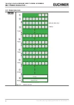
Key for Figure 3: Output structure
System status (1 byte)
B0 = 0: MSC offline
B0 = 1: MSC online
B1 = 1: Diagnostics available
B1 = 0: No diagnostics available
B2 = 1: Error present
B2 = 0: No error
Reserved area (1 byte)
Inputs State (16 bytes)
Each module has a number of bits to suit the number of physical inputs.
The following applies:
Ì
The modules MSC-CB/MSC-CB-S, FI8, FI8FO2, FI8FO4S, SPM0, SPM1 and SPM2 occupy 1 byte.
Ì
The modules FI16 and FM4 occupy 2 bytes.
Ì
The position of the bytes corresponds to the sequence: MSC-CB/MSC-CB-S, FI8FO2, FI16, FI8, FM4,
SPM2, SPM1, SPM0, FI8FO4S.
Ì
If there are 2 modules of the same type, the order is based on the node number.
Copy of the fieldbus inputs
(4 byte)
Used for feedback to the PLC
Status of the fieldbus outputs
(FIELDBUS PROBE) (4 bytes)
Each bit represents the status of a fieldbus output in the project plan. Max. 32 fieldbus output bits can be
used.
Status of OSSD/relay (4
bytes)
Each bit represents the status of an OSSD/relay. The position of the bits corresponds to the sequence:
MSC-CB/MSC-CB-S, FI8FO2, AC-FO2, AC-FO4, AZ-FO4, AZ-FO4O8, AH-FO4SO8, FI8FO4S.
Reserved for the status of
the analog inputs (64 bytes)
Diagnostics (64 bytes)
Each input or safety output function block is linked to the diagnostic code. The system exports 2 bytes on
the fieldbus for every diagnosis:
Ì
The index for the related I/O
Ì
The diagnostic code
NOTICE
Refer to the “Diagnostics” chapter in this manual for more information about the indices of the I/Os
and the diagnostic codes. If I/O is “OK,” the system exports two bytes to the fieldbus with
Ì
0 as index value
Ì
Diagnostic code OK (0x80)
NOTICE
If a fieldbus module is used in the MSC system, the EUCHNER Safety Designer report contains a table
with the I/O index for all inputs, the fieldbus input, the fieldbus output (PROBE) and the safety outputs
in the circuit diagram.
The maximum number of inputs that can be administered in an MSC system is 128, which is why the size of the sub-section
“Inputs States” is 16 bytes (128/8).
The maximum number of safety outputs (OSSD/relay) that can be administered in an MSC system is 32, which is why the
size of the sub-section on the OSSD/relay status is 4 bytes (32/8).
FW < 2.0
The scope of the sub-sections “Inputs States” and the OSSD/relay status depends on the hardware
configuration in the MSC system. The sub-section on the OSSD/relay status is limited to 2 bytes here.
The reserved areas are not transmitted, and the Diagnostics sub-section comprises only 2 bytes.
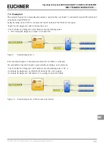
The input and output structures can be graphically depicted in the Bus Configurator – User Interface, see Figure 4.


