


ITX-E8 User`s Manual
19
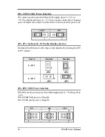
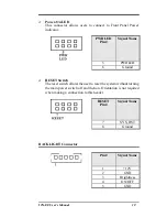
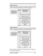
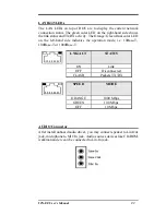
Power-On LED
This connector allows users to connect to Front Panel Power
indicator.
PWR LED
Pin #
Signal Name
5
PWRLED
6
Ground
RESET Switch
The reset switch allows the user to reset the system without turning
the main power switch off and then on. Orientation is not required
when making a connection to this header.
RESET
Pin #
Signal Name
7 SYS_RST
8 Ground
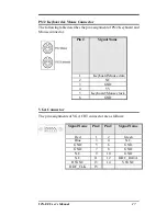
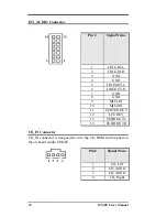
BACKLIGHT Connector
Pin #
Signal Name
1 +12V
2 GND
3 Brightness
4 ON/OFF
5 GND
Содержание ITX-E8
Страница 1: ...I IT TX X E E8 8 INDUSTRIAL MOTHERBOARD User s Manual Version 1 0...
Страница 10: ...2 ITX E8 User s Manual Chapter 1 Features Specifications Features 3 Specifications 4...
Страница 16: ...8 ITX E8 User s Manual This page is intentionally left blank...
Страница 17: ...ITX E8 User s Manual 9 Chapter 2 Jumper setting Connectors Jumpers on the ITX E8 10 Connectors on the ITX E8 16...
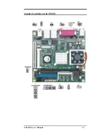
Страница 19: ...ITX E8 User s Manual 11 Jumper Locations on the ITX E8...
Страница 25: ...ITX E8 User s Manual 17 Connector Locations on the ITX E8 1 2...
Страница 84: ...76 ITX E8 User s Manual CHAPTER 4 Appendix I O Port Address Map 77 Interrupt Request Lines IRQ 78 POST Beep 79...