


18
ITX-E8 User`s Manual
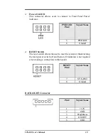
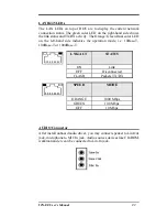
Front Panel Connector
The front panel of the case has a control panel, which provides light
indication of the computer activities and switches to change the
computer status.
RESET PWR HDD PWR
LED LED BTN
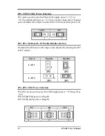
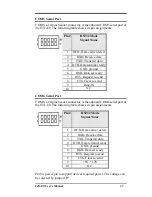
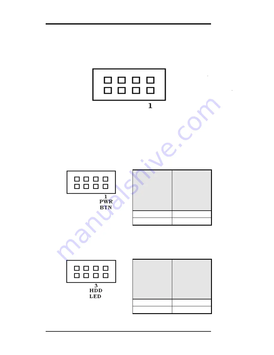
ATX Power ON/OFF Button
This 2-pin connector acts as the “Power Supply On/Off Switch”
on the ITX-E8 main board. When pressed, the switch will force
the Main board to power on. When pressed again, it will force the
main board to power off.
PWR BTN
Pin #
Signal Name
1
5VSB
2
PWRBTN
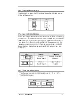
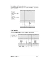
IDE Hard Disk LED Connector
This connector connects to the hard drive activity LED on control
panel. This LED will flash when the HDD is being accessed.
IDE LED
Pin #
Signal Name
3
VCC
4
HDDLED
Содержание ITX-E8
Страница 1: ...I IT TX X E E8 8 INDUSTRIAL MOTHERBOARD User s Manual Version 1 0...
Страница 10: ...2 ITX E8 User s Manual Chapter 1 Features Specifications Features 3 Specifications 4...
Страница 16: ...8 ITX E8 User s Manual This page is intentionally left blank...
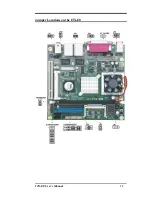
Страница 17: ...ITX E8 User s Manual 9 Chapter 2 Jumper setting Connectors Jumpers on the ITX E8 10 Connectors on the ITX E8 16...
Страница 19: ...ITX E8 User s Manual 11 Jumper Locations on the ITX E8...
Страница 25: ...ITX E8 User s Manual 17 Connector Locations on the ITX E8 1 2...
Страница 84: ...76 ITX E8 User s Manual CHAPTER 4 Appendix I O Port Address Map 77 Interrupt Request Lines IRQ 78 POST Beep 79...