409-35011
Rev D
77
of 83
NOTE
The rear of the contour blade has a small notch. You can help lift the rear of the contour blade by using a small screwdriver to
pry at that notch.
5. Place a new blade over the dowel pins and tighten the screw securely.
6. Repeat for the other two blades.
Replacing the cutting wheels
Preparing the machine for tooling changeover
on page 73).
2. Remove the quick-change arm assembly from the machine (see
on page 74).
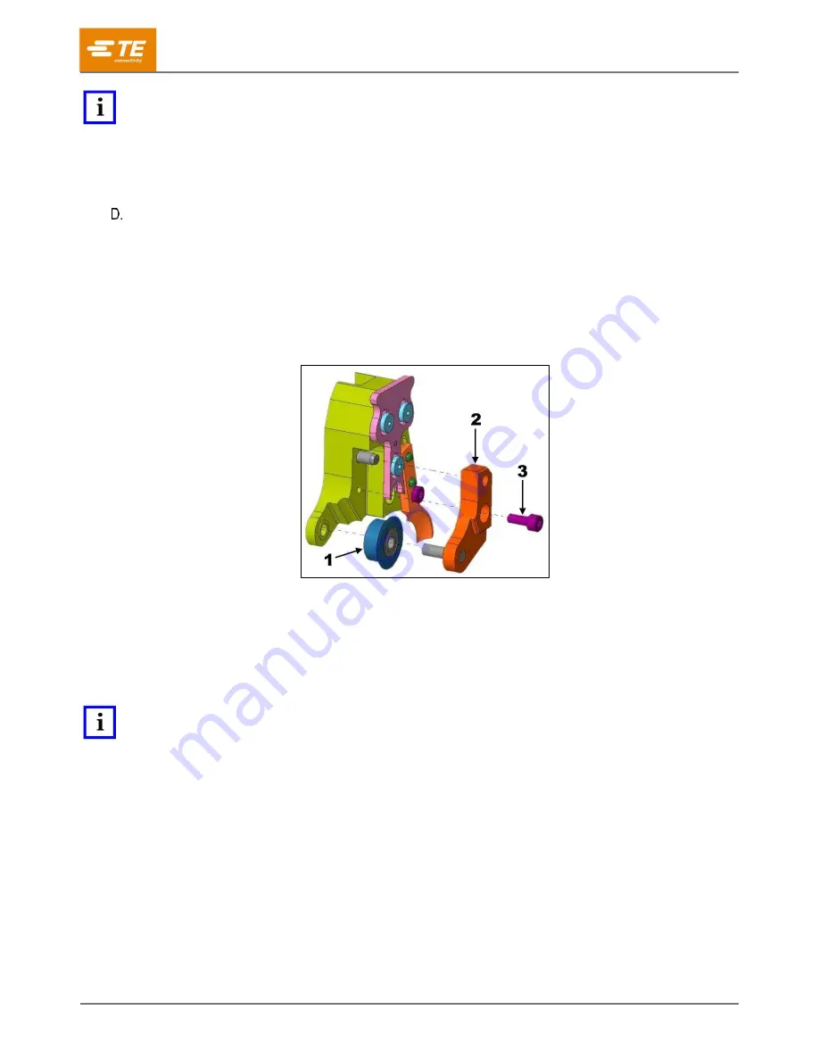
3. Using a 3 mm hex-head wrench, remove the M4 socket head cap screw that holds the cutting arm
cap in place (Figure 98).
Figure 98: Parts of the quick-change arm assembly
1
Cutting wheel
2
Cutting arm cap
3
M4 socket head screw
4. Remove the cutting wheel assembly, taking note of the wheel orientation.
5. Place the new cutting wheel assembly onto the cutting arm cap in the correct orientation.
NOTE
The cutting wheel can only be installed in one orientation. If cutting arm cap does not fit, check the orientation of the cutting
wheel.
6. Carefully install the cutting arm cap onto the cutting arm.
7. Insert the M4 socket head cap screw and tighten securely.
8. Repeat for the other two wheels.


