ETAS
Hardware Description
XETK-S30.0 - User’s Guide
17
4
Hardware Description
In this chapter, the function blocks of the XETK-S30.0 are explained in detail.
4.1
Architecture
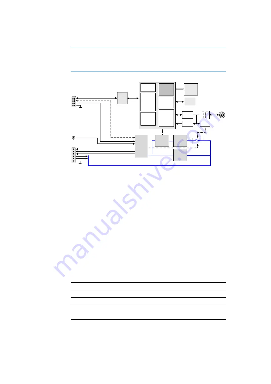
Fig. 4-1 shows the block diagram of the XETK-S30.0.
Fig. 4-1
XETK-S30.0 Architecture
While the microcontroller accesses the program data (not the program code)
out of the data emulation memory provided by the microcontroller, the content
of the data emulation memory can simultaneously be modified by the calibra-
tion and development system through the XETK Ethernet interface. This pro-
cess enables adjustments of parameters, characteristic lines and maps
through the calibration and development system. Using an additional measure-
ment data memory area, the ECU microcontroller can provide data to the cali-
bration and development system by buffering the data (DISTAB13 or
DISTAB17) and triggering the XETK to read the data via JTAG. The XETK then
reads, buffers, processes and sends this measured data to the PC.
If no additional measurement data memory is available, the XETK-S30.0 can
alternatively read the data to be measured directly from the microcontroller’s
memory. This process is Triggered Direct Measurement (TDM) with DISTAB13
or DISTAB17.
The 100 Mbit/s XETK Ethernet interface provides communication with the PC.
ETK Connector Description
CON1
XETK Ethernet interface (ETAS module or PC)
CON2
ECU Interface
CON3
ECU EDRAM Sense port
CON4
Power supply
XCP on
Ethernet
Interface
SRAM
System
Functions
Trigger
Unit
100
MBit/s
Automatic
Power On
Power Supply Sense Ports
ECU Reset
DMA
MCU
Core
Ethernet
MAC
Flash
Loader
ECU
Access
Unit
Data
Flash
ECU -
Connector
Time
Sync.
Traffic
Detection
Ethernet
Phy
I/O -
Buffers
FPGA
Power -
Connector
Sense -
Port
JTAG / DAP
ECU VDDPR
ECU
Reset &
Power
Control
Power
Supply
Monitoring
Power
Supply
3.0 ... 36V
Standby
Power
Supply
3.0 ... 36V
+U-Batt
UBATT1
UBATT2
ECU Power Supply (2x)
CALWAKEUP


