Hardware
11
2
Hardware
This chapter describes the individual function units of the ES4455.1 Load
Board in more detail.
These are:
• "Numbering the Loads on an ES4455.1 Load Board" on page 11
– "Load Signals to the Backplane" on page 12
• "Current Transducers" on page 13
– "Configuring the Current Transducers" on page 13
– "Calibration" on page 15
– "Overcurrent Protection of the Measure Outputs" on page 15
• "Digital Current Signals" on page 15
– "Configuring Current Measuring" on page 16
– "LED Display" on page 16
– "Acoustic Signals" on page 16
• "Settings in LABCAR-RTC" on page 17
2.1
Numbering the Loads on an ES4455.1 Load Board
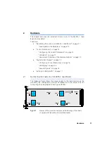
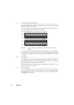
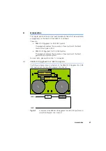
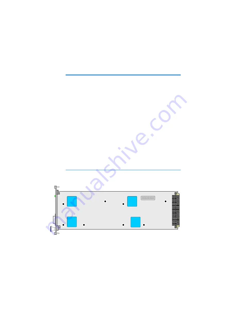
The following figure shows the power supply to the load modules via the
standoffs, the corresponding current transducers and the jumper strip for
configuring an analog/digital current signal (JP200).
Fig. 2-1
Names of the Load Connectors and Numbering of the Loads
(Component Side without Assembled Loads)
Load 1+
Load 1-
Load 4+
Load 4-
Load 2+
Load 2-
Load 3+
Load 3-
I/I
Load 2
I/I
Load 3
I/I
Load 1
I/I
Load 4
JP200
Содержание ES4455.1
Страница 1: ...ES4455 1 Load Board User s Guide ...
Страница 10: ...Introduction 10 ...
Страница 24: ...Technical Data 24 ...
Страница 26: ...ETAS Contact Addresses 26 ...


