Pin Assignment and Display Elements
19
3
Pin Assignment and Display Elements
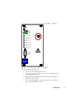
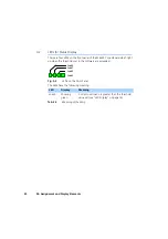
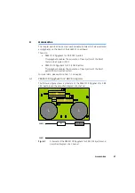
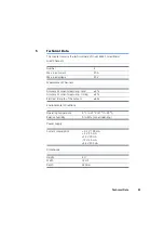
This chapter contains a description of the pins and LEDs on the front panel of
the ES4455.1 Load Board.
3.1
“Threshold Calibration Connection” Connector
The thresholds for digitizing the current signal, which can be set on the front
panel using potentiometers, can be tapped at the “Threshold Calibration
Connection” connector.
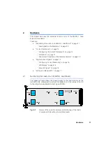
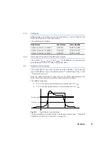
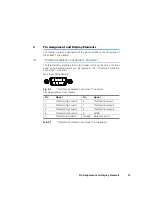
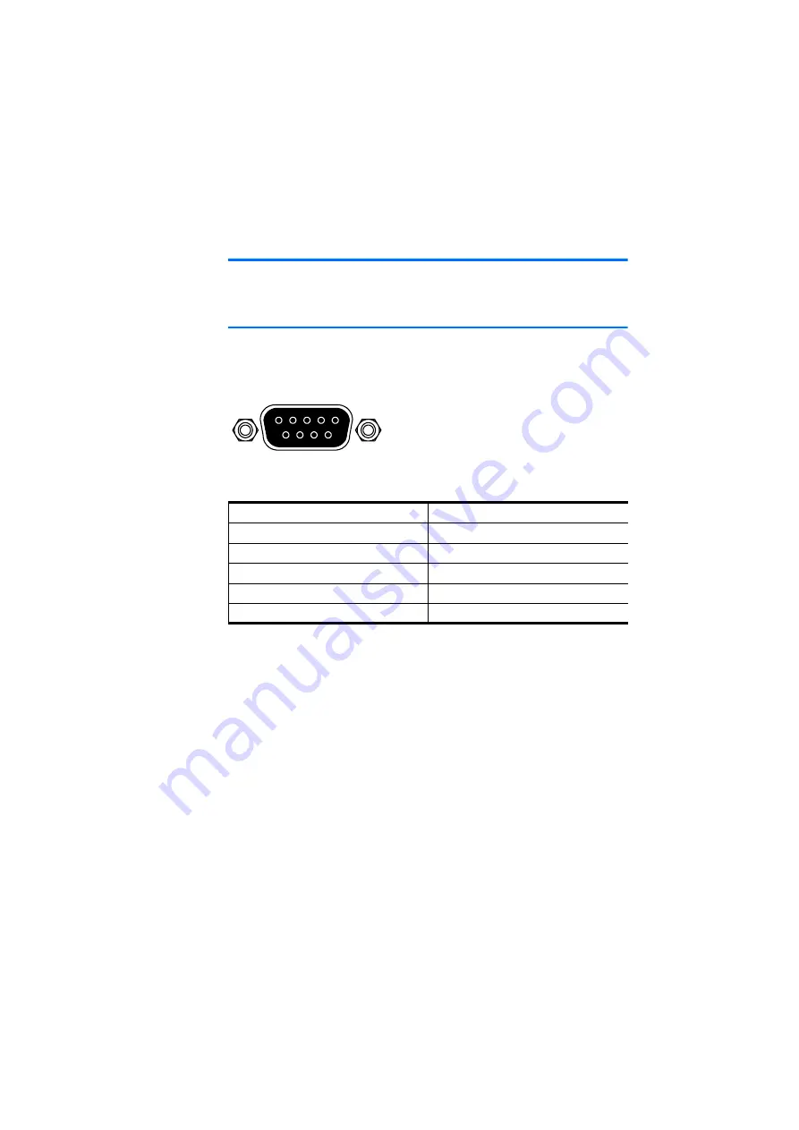
Type: 9-pin DSUB (female)
Fig. 3-1
“Threshold Calibration Connection” Connector
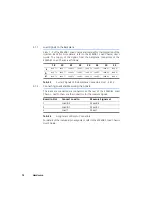
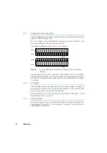
The pin assignment is as follows:
Tab. 3-1
“Threshold Calibration Connection” Pin Assignment
Pin
Signal
Pin
Signal
1
Threshold high Load 0
6
Threshold low Load 1
2
Threshold high Load 1
7
Threshold low Load 2
3
Threshold high Load 2
8
Threshold low Load 3
4
Threshold high Load 3
9
AGND
5
Threshold low Load 0
Housing
Protective earth
5 4
3 2 1
9 8 7 6
Содержание ES4455.1
Страница 1: ...ES4455 1 Load Board User s Guide ...
Страница 10: ...Introduction 10 ...
Страница 24: ...Technical Data 24 ...
Страница 26: ...ETAS Contact Addresses 26 ...

