ES1652.2 Carrier Board for Signal Conditioning Circuits - User’s Guide
9
ETAS
Hardware Description
2
Hardware Description
This chapter contains information on the following topics:
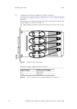
– "Configuration of the Input Voltage of the DC/DC Converters"
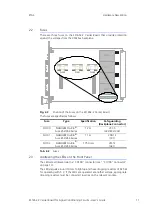
• "Fuses" on page 11
• "Addressing the LEDs on the Front Panel" on page 11
2.1
Power Supply
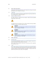
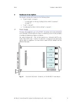
To power the piggybacks, up to four DC/DC converters can be accommodated
on the ES1652.2 Carrier Board for Signal Conditioning Circuits for the purposes
of voltage stabilization and galvanic isolation.
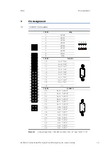
The output voltages DC1 - DC4 of the converters are connected with the con-
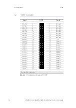
nector strip CO101 (see ""CO101" Connector" on page 14) and can thus be
used to power a piggyback. The converters are powered with voltages from the
VMEbus backplane.
Fig. 2-1
Position of the DC/DC Converters on the ES1652.2 Carrier Board
IN
1..
9
OU
T
1
..1
5
IC100
IC101
IC102
IC103
CO
100
CO1
0
1
Содержание ES1652.2
Страница 1: ...ES1652 2 Carrier Board for Signal Conditioning Circuits User s Guide...
Страница 4: ...ES1652 2 Carrier Board for Signal Conditioning Circuits User s Guide 4 Contents ETAS...
Страница 12: ...ES1652 2 Carrier Board for Signal Conditioning Circuits User s Guide 12 Hardware Description ETAS...
Страница 16: ...ES1652 2 Carrier Board for Signal Conditioning Circuits User s Guide 16 Technical Data ETAS...
Страница 18: ...ES1652 2 Carrier Board for Signal Conditioning Circuits User s Guide 18 ETAS Contact Addresses ETAS...
Страница 20: ...ES1652 2 Carrier Board for Signal Conditioning Circuits User s Guide 20 Index ETAS...


