www.etsolar.com
Subject to technical modifications without notice. 2016 © ET Solar Group
www.etsolar.com
Subject to technical modifications without notice. 2016 © ET Solar Group
10
11
www.etsolar.com
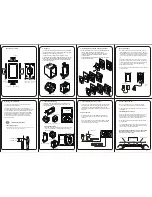
5.2 Wire
5.3 General electrical installation
When connecting parallel modules strings to the distribution box, use proper
third-party PV system connectors with suitable length PVF type cable which are
qualified for EN50521 and 2PFG1169. All field wiring cables must have large enough
cross-sectional areas approved for use at the maximum short-circuit current of the PV
module. ET Solar recommends that installers use only sunlight resistant cables (PVF1
type) for direct current (DC) wiring in PV systems. The recommended minimum wire
size should be 4 mm² and must be subject to the local national codes and regulations.
The connecting cables must not cross each other and must be kept away from direct
sunlight, heat source and any static pool of water. The cables should be secured by
the modules mounting structure and should maintain a distance of at least 25 mm
from one another with no possibility of coming into contact.
The connectors should be kept dry and clean. Do not attempt to make electrical
connections between wet, soiled, or otherwise faulty connectors. Faulty connections
can result in electrical shocks and arcs.
Expect for equipment grounding, ET Solar recommends the negative pole of PV
module array is connected to earth during all PV system installations. That will keep
optimal performance of PV Power Plants, which are located in a hot, high humidity
climate and high Maximum System Voltage.
The junction box on each PV module has two wires that terminate in a male and a
female connector. When the modules are to be connected in series, the male
connector should be plugged into the female connector of the neighboring module
while the female connector should be plugged into the male connector of the other
neighboring module.
Do not use modules of different configurations in the same system.
This module is supplied with Multi Contact connectors for electrical connections.
Refer to local code to determine appropriate types and temperature ratings of
conductors. Wiring should be #12 AWG, 4 mm² (minimum) and must be temperature
rated at 90 °C (minimum).
Completely cover system modules with an opaque material to prevent electricity from
being generated while disconnecting conductors.
Refer to local code to determine over current, conductor ampacity and size
requirements.
Installation shall be in accordance with local code.
PV module grounding with lay in lug (φ4mm grounding holes)