background image

60

FREQUENTLY ASKED QUESTIONS (FAQ)

MAINTENANCE PROCEDURES

Replacing the Hard Disk Drive

WARNING:  


Be sure to turn off the power of the Touch Terminal before installing or removing 

any components.

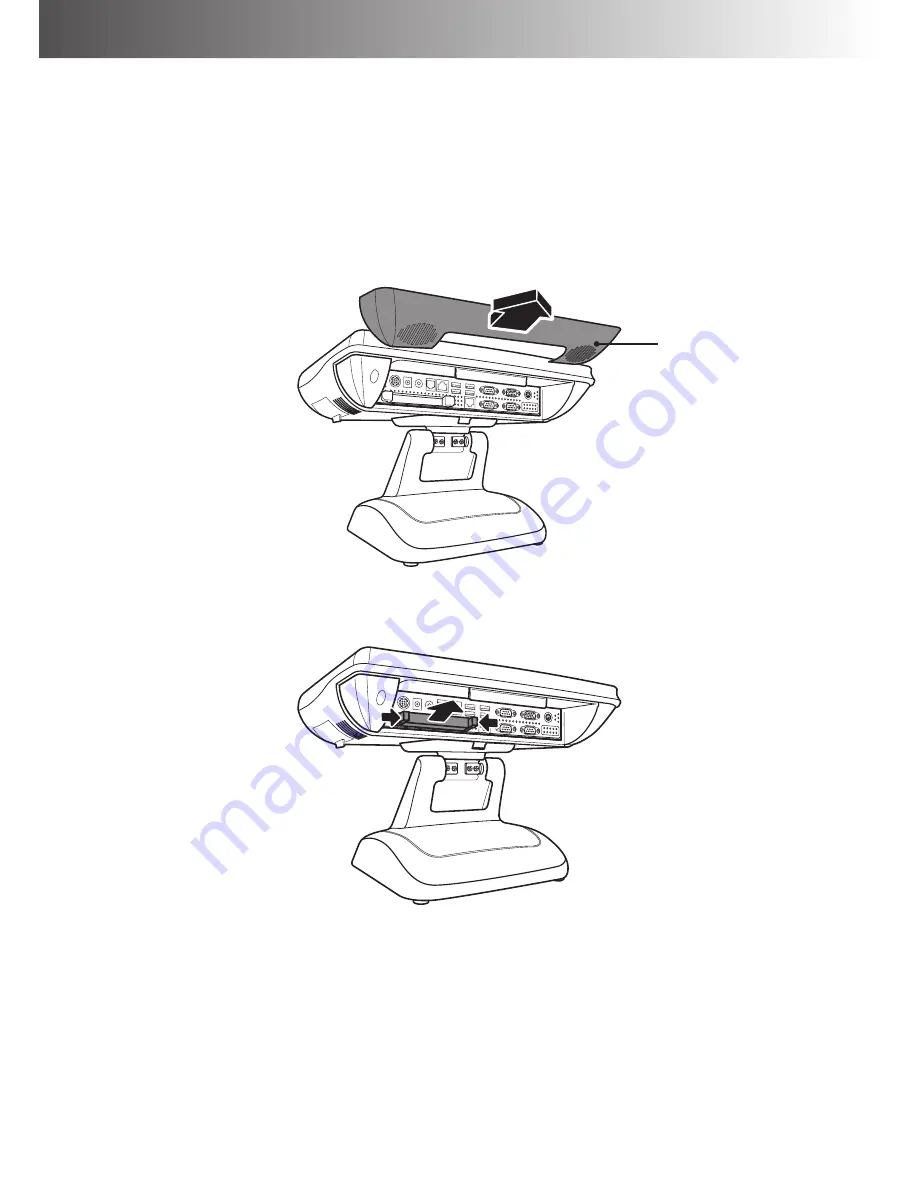
To replace the hard disk drive, do the following:

1.  Position the LCD panel facing up and remove the connectors cover.

Connectors cover

2.  Press both sides of the HDD clip inwards to release lock. Then pull the HDD out from the 

slot.

3. 

Replace a new hard disk drive. Then follow the above-mentioned steps in reverse to finish 

the replacement.

Содержание B-615

Страница 1: ...Bravo Series B 615 B 615S B 815 Version 1 0 User Manual...

Страница 2: ...o be shipped in the future Follow the product and warning label instructions Any changes or modifications that do not follow the instructions in this manual will void this product s warranty Power Sup...

Страница 3: ...he screen or the casing of the terminal Chemical cleaners have been reported to cause damage on the screen of the terminal Warning and Attention The technical descriptions and specifications of the eq...

Страница 4: ...r there is no guarantee that interference will not occur in a particular installation If this equipment does cause harmful interference to radio or television reception which can be determined by swit...

Страница 5: ...not be disposed of or dumped with your other household waste You are liable to dispose of all your electronic or electrical waste equipment by relocating over to the specified collection point for re...

Страница 6: ...28 Power Switch Board Connector 29 Voltage Output Definition 30 Cash Drawer Controller Register 32 RS232 Control B 615 B 615S 32 GPIO Control B 615S B 815 32 Calibrating the Touch Screen in Windows 33...

Страница 7: ...the Laser Scanner Optional 55 Connecting to POS Peripherals 56 Chapter 4 Maintenance Procedures 58 Replacing the System Core Engine 58 Replacing the Hard Disk Drive 60 Chapter 5 Frequently Asked Ques...

Страница 8: ...ility by offering superior customer experience Package Contents Before setting up your Touch Terminal check that the package contains the following items If any of the items is missing or damaged cont...

Страница 9: ...his section illustrate the components including input and output ports located at the front and rear of your Touch Terminal Front View B 615 B 615S B 815 USB USB USB DK COM6 VGA K B COM1 COM2 COM4 LAN...

Страница 10: ...View 1 5 3 4 2 3 Without Stand With Stand No Description 1 VESA holes 2 MSR module compartment 3 Speakers 4 VESA routing plate 5 Control panel a 2 USB ports b Power button c Brightness control buttons...

Страница 11: ...INTRODUCTION 11 Physical Dimensions 347 97 379 19 198 77 148 5 299 59 12 218 33 75...

Страница 12: ...DDR3 RAM 2 slots Up to 8GB BIOS Phoenix Award BIOS AMI 64Mbit SPI BIOS AMI 64Mbit UEFI BIOS Graphic Memory Shared memory up to 224MB HDD 1 x 2 5 SATA HDD or 1 x 1 8 2 5 SSD SATA DOM Support 1GB to 16G...

Страница 13: ...x D Desktop model 336 348 200mm VESA model 269 348 75mm System Weight Desktop model 10Kg VESA model 7Kg Safety Environment Product Certification CE FCC CCC CB BSMI LVD Certificated Operation Temperat...

Страница 14: ...nglish Russia English Japanese Traditional Chinese Simplified Chinese Dot Size 0 93 W x 1 11 H mm Input power type 5 VDC Interface RS232 Vacuum Fluorescent Display VFD Model no CM 5000 Polarizer color...

Страница 15: ...3 single dual triple tracks of magnetic card support ANSI ISO Standards7810 7811 1 5 7812 7813 USB HID Keyboard mode interface iButton Detector Dallas DS1990A compliment With leading ending programmi...

Страница 16: ...Source 650 nm visible laser diode VLD Depth of Field 0 200 mm UPC EAN 100 PCS 90 Number of Scan Lines 20 Scan Pattern 5 directions of scan field Scan Rate 1 200 scans per second Indicators LED Two co...

Страница 17: ...urned off Otherwise electric shock may occur and may void the warranty For systems preloaded with WEPOS POSReady Windows Embedded on the HDD O S pre installed as an option the manufacturer provides an...

Страница 18: ...output USB1 USB 2 connector KB1 PS 2 keyboard connector OUT4P1 2 DC Power output for S ATA HDD SSD CN1 M B signal convergence connector CN2 S ATA connector CN3 S ATA connector CN4 Gigabit LAN 2 USB c...

Страница 19: ...9 VOLTAGE SELECT 1 3 5 2 4 6 1 2 0V 3 4 5V 5 6 12V Default 0V JP6 COM 1 D SUB PIN9 VOLTAGE SELECT 1 3 5 2 4 6 1 2 0V 3 4 5V 5 6 12V Default 0V JP7 COM 3 D SUB PIN9 VOLTAGE SELECT 1 3 5 2 4 6 1 2 0V 3...

Страница 20: ...d DC 12V 2A B 615S Connector Jumper Description JP2 J4 SATA Pin7 Setting SATA Dom Only JP3 LCD Panel Power Selection JP4 Flash Descriptor Security Override Factory use only JP5 Clear CMOS Contents JP6...

Страница 21: ...in 2 3 Short Closed GND JP3 LCD Panel Power Selection JP3 Setting Function Pin 1 2 Short Closed 5V Pin 2 3 Short Closed 3 3V JP4 Flash Descriptor Security Override Factory use only JP4 Function Open D...

Страница 22: ...2 3 Short Closed 5V JP9 CN7 Cash Drawer Power Selection JP9 Setting Function Pin 1 2 Short Closed 24V Pin 2 3 Short Closed 12V JP10 COM6 CN2 RS232 RI 5V 12V Power Setting JP10 Setting Function Pin 1...

Страница 23: ...RI 5V 12V Power Setting JP13 Setting Function Pin 1 2 Short Closed RI Pin 3 4 Short Closed 5V Pin 5 6 Short Closed 12V JP14 CN1 PS 2 KeyBoard Power Selectionn JP14 Setting Function Pin 1 2 Short Clos...

Страница 24: ...only J11 J12 DDR3 SO DIMM J13 80 Port Debug Tool Connector Factory use only J14 Parallel Port Connector JP3 Clear CMOS Contents JP4 J6 SATA Pin7 Setting SATA Dom Only JP5 LCD Panel Power Selection JP6...

Страница 25: ...orts Pin1 Setting by JP9 CN7 Cash Drawer Pin4 Setting by JP6 CN6 HD Audio Connector Line out only CN9 DC Power Jack 12V 2A Output CN10 DC Power DIN 4P 24V Input JP3 Clear CMOS Contents JP3 Setting Fun...

Страница 26: ...sed 5VSB Pin 2 3 Short Closed 5V JP8 CN4 USB Power Selection JP8 Setting Function Pin 1 2 Short Closed 5VSB Pin 2 3 Short Closed 5V JP9 COM4 CN3 RS232 RI 5V 12V Power Setting JP9 Setting Function Pin...

Страница 27: ...232 RI 5V 12V Power Setting JP12 Setting Function Pin 1 2 Short Closed RI Pin 3 4 Short Closed 5V Pin 5 6 Short Closed 12V JP13 CN8 PS 2 KeyBoard Power Selection JP13 Setting Function Pin 1 2 Short Cl...

Страница 28: ...tion JUSB1 USB port for POS input device JUSB2 USB port for USB Touch CN2 COM3 connector for LCM VFD display CN3 LCD backlight inverter connector CN4 2x10 LVDS connector CN5 COM2 connector for RS 232...

Страница 29: ...l Type A LCD brightness is controlled by physical button Connector Jumper Description S1 Power On switch UP1 LCD Brightness DOWN1 LCD Brightness CN1 2 USB connector J1 Signal connector Type B LCD brig...

Страница 30: ...not plug in or unplug any connector except USB devices when the power is on The current loading for all COM ports should not exceed DC 5V 3A and DC 12V 2A B 615S Connector with Voltage Output Location...

Страница 31: ...Convergence Board DC5V only COM 4 for RJ45 Main Board DC5V DC12V select by jumper COM 5 for Touch Signal Convergence Board DC12V DC24V select by jumper COM 6 for extension interface Main Board DC5V DC...

Страница 32: ...dress 288 2F0 Baud rate 1200 9600 Open command 01h 07h Respond command 02h 02h GPIO Control B 615S B 815 The Cash Drawer Controller use one I O address to control the Cash Drawer Register Location 48C...

Страница 33: ...HE INSTALLATION 33 Calibrating the Touch Screen in Windows Setting 1 Beep Configure the Touch sound Frequency Set the sound type Duration Audio sound length 2 Linearization style Set 9 point or 25 poi...

Страница 34: ...nts calibration After the 25 points calibration data is cleared the 4 points calibration data also becomes invalid Therefore the 4 points calibration must be done 3 Linearization Linearization 25 or 9...

Страница 35: ...l Type A Setting by physical button USB 1 No Item Function 1 Brightness Press the Brightness button to decrease brightness The setting will be saved 6 seconds after releasing the button Brightness Pre...

Страница 36: ...ION Type B Setting by BIOS Boot Menu B 615 To adjust the LCD brightness do the following 1 Press F2 when the system boot Then select the Intel tab 2 In the Intel menu select LPC Control Sub Menu item...

Страница 37: ...PREPARING FOR THE INSTALLATION 37 4 On the Brightness Control Level option set the desired brightness level setting...

Страница 38: ...615S To adjust the LCD brightness do the following 1 Press F2 when the system boot Then select the Advanced tab 2 In the Advanced menu select LVDS Configuration 3 On the Panel Brightness option set t...

Страница 39: ...To adjust the LCD brightness do the following 1 Press F2 when the system boot Then select the Advanced tab 2 In the Advanced menu select F81866 Super IO Configuration 3 On the Panel Brightness option...

Страница 40: ...Touch Terminal on a soft and flat surface with the LCD panel facing the down Detach the connectors cover 2 Align and install the power adapter between the guide holes for the adapter bracket screws 3...

Страница 41: ...tall the connectors cover To remove the power adapter do the following WARNING Be sure to turn off the power of the Touch Terminal before making any connection or disconnection 1 Place the Touch Termi...

Страница 42: ...NSTALLATION 2 Disconnect and release the power cable 3 Remove the four screws I M3 5 from the power adapter bracket 4 Remove the power adapter bracket 5 Remove the power adapter Power adapter bracket...

Страница 43: ...disconnection To install the network cable do the following 1 Place the Touch Terminal on a soft and flat surface with the LCD panel facing the down Detach the connectors cover Connectors cover 2 Ins...

Страница 44: ...tion or disconnection 1 Place the Touch Terminal on a soft and flat surface with the LCD panel facing the down Detach the connectors cover 2 Rotate the stand panel to access the screws securing the st...

Страница 45: ...ATION 45 3 Remove the following items a Connectors cover b Four screws P M4 10 securing the stand panel to the Touch Terminal c VESA compartment cover Connectors cover VESA compartment cover 4 Release...

Страница 46: ...ection To configure the COM port voltage setting to 5V refer to Main Board Jumpers and Connectors on page 18 1 Align the customer display with the Touch Terminal and route the cable through the cable...

Страница 47: ...HARDWARE INSTALLATION 47 4 Secure the panel stand assembly to the Touch Terminal with the four screws P M4 10 5 Connect the customer display s interface cable to the RJ 45 COM port on Touch Terminal...

Страница 48: ...48 HARDWARE INSTALLATION 6 Install the connectors cover and customer display compartment Customer display compartment...

Страница 49: ...ection 1 Align the secondary LCD display with the Touch Terminal and route the cables through the cable compartment on Touch Terminal 2 Secure the secondary LCD display to the Touch Terminal with the...

Страница 50: ...50 HARDWARE INSTALLATION 5 Connect the secondary LCD display s power cable and VGA cable to the corresponding ports on Touch Terminal 6 Install the connectors cover and customer display compartment...

Страница 51: ...any connection or disconnection To install the MSR onto the Touch Terminal do the following 1 Open the MSR module compartment and remove the small chip off the compartment cover 2 Firmly connect the...

Страница 52: ...52 HARDWARE INSTALLATION 3 Secure the MSR module to the Touch Terminal using the three screws F M3 16...

Страница 53: ...manufacturer Wall mount kits are sold separately Mount on the wall Mount on Touch Terminal 1 Drill four small holes on the mounting location and insert the plastic washers into the holes 2 Place the...

Страница 54: ...54 HARDWARE INSTALLATION 3 Attach the bracket onto the Touch Panel using four screws P M4 10 4 Align and hook the Touch Terminal to the wall bracket and then push down to secure it into place...

Страница 55: ...Attach the scanner module to the scanner bracket using three screws P M3 6 2 Attach the scanner bracket and the VESA mount bracket onto the Touch Terminal using four screws P M4 10 3 Connect the USB c...

Страница 56: ...AN Connect to Ethernet 5 USB Port Connect to USB POS device 6 HDD Bay Connect to a SATA HDD 7 PS2 KB only Connect to a programmable POS keyboard 8 VGA Port Connect to a 2nd LCD display 9 COM 5 Connect...

Страница 57: ...to Ethernet 5 USB Port Connect to USB POS device 6 HDD Bay Connect to a SATA HDD 7 PS2 KB only Connect to a programmable POS keyboard 8 VGA Port Connect to a 2nd LCD display 9 COM 4 Connect to RJ 45 R...

Страница 58: ...stem Core Engine WARNING Be sure to turn off the power of the Touch Terminal before making any connection or disconnection To replace the system core engine do the following 1 Position the LCD panel f...

Страница 59: ...captive screw that secures the system core engine onto the Touch Terminal 4 Pull the system core engine out from the compartment 5 Replace the system core engine Then follow the above mentioned steps...

Страница 60: ...ny components To replace the hard disk drive do the following 1 Position the LCD panel facing up and remove the connectors cover Connectors cover 2 Press both sides of the HDD clip inwards to release...

Страница 61: ...s or load SETUP Default after flashing BIOS If the system remains unstable clear CMOS to solve the problem Steps On the Save Exit page select Restore Defaults then select Yes Select Save Changes and R...

Страница 62: ...n Select Item Enter Select Change Field F1 General Help F2 Previous Values F3 Optimized Default F4 Save Changes and Reset Discard Changes and Reset Save Options Save Changes Discard Changes Restore De...

Страница 63: ...4 Press F2 to enter CMOS setting and load optimized defaults 5 Save changes and reboot the system Question 3 How to use Boot Menu Answer To use the Boot Menu do the following 1 Press F10 B 615 B 615S...

Отзывы: