ESPROS epc610 Скачать руководство пользователя страница 6

2. Hardware

The purpose of this section is to introduce to the user the epc610 camera module and the functional use of the epc600/610 Evaluation Kit.
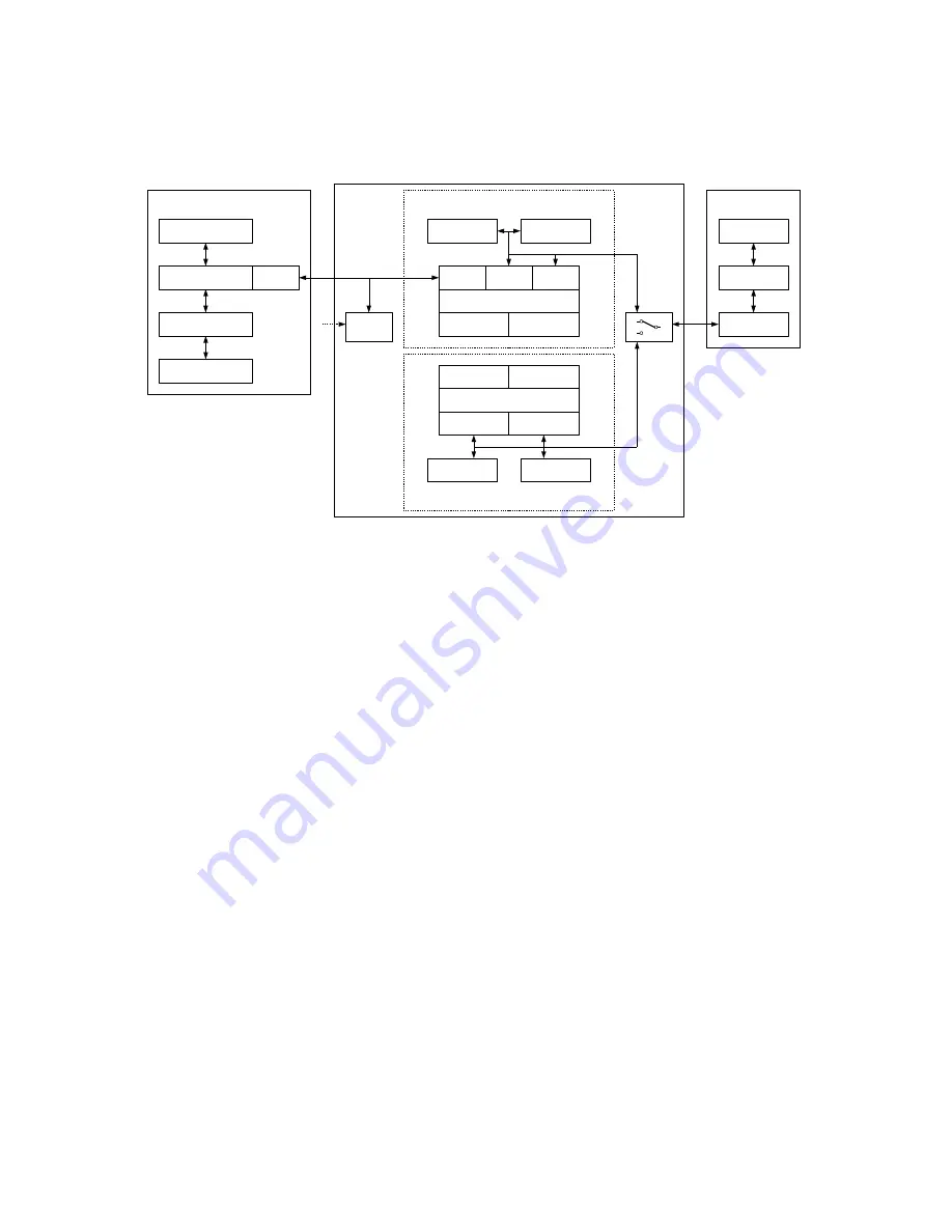
2.1. Block diagram

The system consists of 3 main parts: A personal computer, the Evaluation Kit mainboard and a camera module (refer to  Figure 6).

Data

memory

Program

memory

USB

interface

2-wire / SPI

interface

I/O

interface

Main-microprocessor

Input switches
Main signaling

Power
supply

epc600 / epc610 evaluation system

epc600 application with PIC10F *

1-button interface

Microprocessor PIC10F206

ICSP connector

2-wire

interface

I/O

interface

Data

memory

Program

memory

Debug connector


Mainboard

Computer

Configuration-

& data files

Application Software

Human interface

GUI

USB

interface

Personal computer

USB

interface

Camera

Config setting

Optics

(optical path)

epc6xx

in operation

Figure 6: Block diagram (* not implemented)

The Personal computer

IBM compatible or Apple (Mac).

Man-machine interface for the operation and visualization of the evaluation system.

Runs the application software.

Stores, reads and writes configuration- and data-files for the application.

Host system for ST ARM 32bit Cortex microprocessor software development.

The mainboard

Two sections with independent microprocessor systems: 

The one for the “epc600 / epc610 evaluation system” (Evaluation) 

The second is a minimal hardware design concept for a Range Finder application with the epc600 (Application with PIC10F).
Not used for the epc610 camera application.

A main switch selects which section will be connected to the camera module.

The mainboard/system is connected to the computer by a USB cable for data communication and power supply.

The power supply generates all of the necessary supply voltages from the USB connection. An additional external USB power supply 
can be added if the PC USB interface is not capable of delivering the necessary power (1'000 mA).

The “epc600/epc610 evaluation system” section supports and gives access to the full functionality of the epc610 devices.

Checks for the correct device identification of the camera.

Configures and controls the camera.

Reads the picture data from the camera and sends it via USB to the computer.

Provides configuration DIP switches and signaling LEDs.

A “debug connector” allows advanced users to download their own application. For more information, refer to the manual of the 
corresponding processor.

The epc610 camera module

Is a fully functional module with the epc610 TOF Imager chip and optics combined.

Connects to the mainboard for power supply, data communication and configuration reading.

Goals and objectives of this Evaluation Kit:

Easy-to-use, plug and play demonstrator to show how epc's TOF products work and which possibilities they offer.

Test kit for engineers, allowing for a first contact with epc's products.

Reference design kit for design and development engineers.

Supports the user during development and testing of his own hard- and software.

© 2014 ESPROS Photonics Corporation

Characteristics subject to change without notice

6 / 26

Manual epc610_Camera - V1.5

www.espros.ch

Содержание epc610

Страница 1: ...with 8x8 pixel epc610 Imager chip Comprehensive application software with graphical user interface to operate the epc610 chip inside the camera Automatic mode with adaptive integration times Manual m...

Страница 2: ...APPLICATION ANY ALTERATION TO THE DEVICES BY THE BUYER INSTALLER OR USER MAY RESULT IN UNSAFE OPERATING CONDITIONS ESPROS photonics AG IS NOT RESPONSIBLE FOR ANY LIABILITY OR WARRANTY CLAIM WHICH RES...

Страница 3: ...mage 18 5 1 9 Integration time and Greyscale resolution Widget Brightness 18 5 1 10 Distance range settings Widget Settings 19 5 1 11 Register map Widget Setting 19 5 1 12 Display refresh rate Widget...

Страница 4: ...epc600 TOF Range Finder chip with 1 4 x 1 4 optical aperture angle including cable P100 223 epc610 Camera Module V1 0 Camera module with an epc610 TOF Imager chip with 8 7 x 8 7 optical aperture angl...

Страница 5: ...0V DC 5 0V 5 typ 25mA max 420mA Power consumption max 2 4W Communication SPI interface 4 wire max 10Mbit s max cable length 0 5m Receiver focal length f0 2 1 mm Receiver f stop 2 2 Operating wavelengt...

Страница 6: ...sed for the epc610 camera application A main switch selects which section will be connected to the camera module The mainboard system is connected to the computer by a USB cable for data communication...

Страница 7: ...igned for verification of datasheet parameters Such tests need a dedicated test environment Not designed for use in final applications 2014 ESPROS Photonics Corporation Characteristics subject to chan...

Страница 8: ...18V 600 R 100 MHz L3 100nF C23 47uH L1 22k R16 47k R5 4k7 R6 15k R7 10uF C22 10nF C24 100R R8 22k R9 1nF C20 10nF C21 0R1 R18 0R1 R17 D4 SFH4059 D5 SFH4059 D6 SFH4059 D8 SFH4059 D9 SFH4059 D10 SFH4059...

Страница 9: ...D10 D11 BAT74 Schottky double diode D1 B340 40V 3A Diode D3 PMV45EN Transistor T1 epc610 epc610 IC1 LTC1983 5 Voltage convertor IC3 LM3478 Voltage regulator IC4 Header 6 Pin dual row J1 47 H Inductor...

Страница 10: ...dules supplied by ESPROS photonics the pin assignment is already done for the correct operation of the module in combi nation with the mainboard For the correct standalone operation of the epc610 came...

Страница 11: ...stallation connect the evaluation kit through the connector J6 USP FS to your PC with the enclosed USB cable Make sure that the power supply selection switch on the evaluation kit is switched to USB F...

Страница 12: ...ode which gives access to the full functionality of the epc610 camera module It requires a host PC that has the application software installed and running Check if the application software is installe...

Страница 13: ...ply options On power up the system loads the microprocessor software and checks which type of camera module is connected The system config ures itself automatically according to the connected camera m...

Страница 14: ...application to from the Evaluation Kit hardware Always use this first before you start any other operation Start Stop Starts or stops the data acquisition Use after the Evaluation Kit hardware has be...

Страница 15: ...e and amplitude The widget shows the numbers and the histogram distributions for the 3D TOF distance values and the ampli tude values 3D modes readout amplitude Brightness mode normalized amplitude sc...

Страница 16: ...visible or accessible once A closing of the external dialog puts back the control widget to the tabs of its control area 5 1 4 Pixel field orientation The pixel field corresponds to the numeration of...

Страница 17: ...signal The background color reflects the quality of the pixel signal Signal quality Background color Readout amplitude excellent green 200 value good yello 100 value 200 bad red value 100 infinity in...

Страница 18: ...ast the way having minimum one pixel white and one black and look not anymore evenly Refer for details to next chapter 5 1 9 Integration time and Greyscale resolution Widget Brightness Figure 21 Brigh...

Страница 19: ...5 1 11 Register map Widget Setting This is a service function for epc s customer support It is not transparent to the user Save registers On request of epc s customer support the user can read the set...

Страница 20: ...the extremely short timeframes that are relevant for TOF there is an inherent temperature dependency that leads to a distance drift Therefore the epc TOF chips have integrated temperature sensors who...

Страница 21: ...Brightness mode Grayscale image The 4 datasets DCS0 DCS3 are the amplitude values of the 4 sequential black white pictures with ambient light 5 1 17 Widget 2D Histogram of distance and DC light 3D mod...

Страница 22: ...ulated readout amplitude values as numbers and histogram distributions Figure 32 The sample values of the 4 integration periods 5 1 19 Log dialog This function allows data logging for offline analysis...

Страница 23: ...sion factor or reflectivity Examples A sheet of white paper has a remission of 90 whereas a dark carpet reflects only 5 Ambient light suppression In real world applications there will always be ambien...

Страница 24: ...MOVING OBJECT REFLECTED LIGHT TIME T1 SAMPLE 1 TIME T2 SAMPLE 2 TIME T3 SAMPLE 3 TIME T4 SAMPLE 4 Figure 34 Measurement cycle with moving object 6 8 Transparent objects Transparent objects may distort...

Страница 25: ...in our tools and respect the large amount of work the owners have done libusb 1 0 Copyright C 2007 2008 Daniel Drake Copyright C 2001 Johannes Erdfelt under LGPL License http www gnu org licenses lgp...

Страница 26: ...of epc Resale of epc products or services with statements different from or beyond the parameters stated by epc for that product or service voids all express and any implied warranties for the associ...

Отзывы: