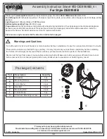
CAUTION: Before installing make certain the AC power
is off and the LED lamp emergency backup unit connector
is disconnected.
PAGE 2 OF 4
EMERGENCY DRIVER
INSTRUCTIONS
Installation
1. Specification of ESL-EMG-2DC Series
See the ESL-EMG-2DC SERIES SPECIFICATION chart below for the model selected.
2. Installing the ESL-EMG-2DC
The ESL-EMG-2DC should be mounted inside the luminaire and is a factory install only.
3. Installing the LED Test Switch
Select a convenient location for the LED Test Switch so that it can be seen after installation. Drill a 1/2" hole for
mounting. Connect the wires from the LED Test Switch to the ESL-EMG-2DC model according to the wiring
diagram on page 3.
ESL-EMG-2DC-5W
ESL-EMG-2DC-9W
ESL-EMG-2DC-15W
ESL-EMG-2DC-25W
MODEL
5 WATTS
9 WATTS
15 WATTS
25 WATTS
13-60 VDC
14-60 VDC
15-60 VDC
25-60 VDC
VOLTAGE OUTPUT
EMERGENCY OUTPUT (CONSTANT)
VOLTAGE OUTPUT
INSIDE THE LUMINAIRE
E
S
L-
EM
G-2
D
C
LED TEST SWITCH
MOUNTING HOLE - Ø0.47"
0.24"
0.98"
10.04"
This product contains a rechargeable nickel-metal hydride battery.
THE BATTERY MUST BE RECYCLED OR DISPOSED OF
PROPERLY TO PREVENT FIRE.
Copyright © 2018 ESL Vision, LLC. All rights reserved. Rev: 08/15/2018