


PCB View and LED Description
3.2 LEDs and DSUB37 Connector in the Slot Bracket
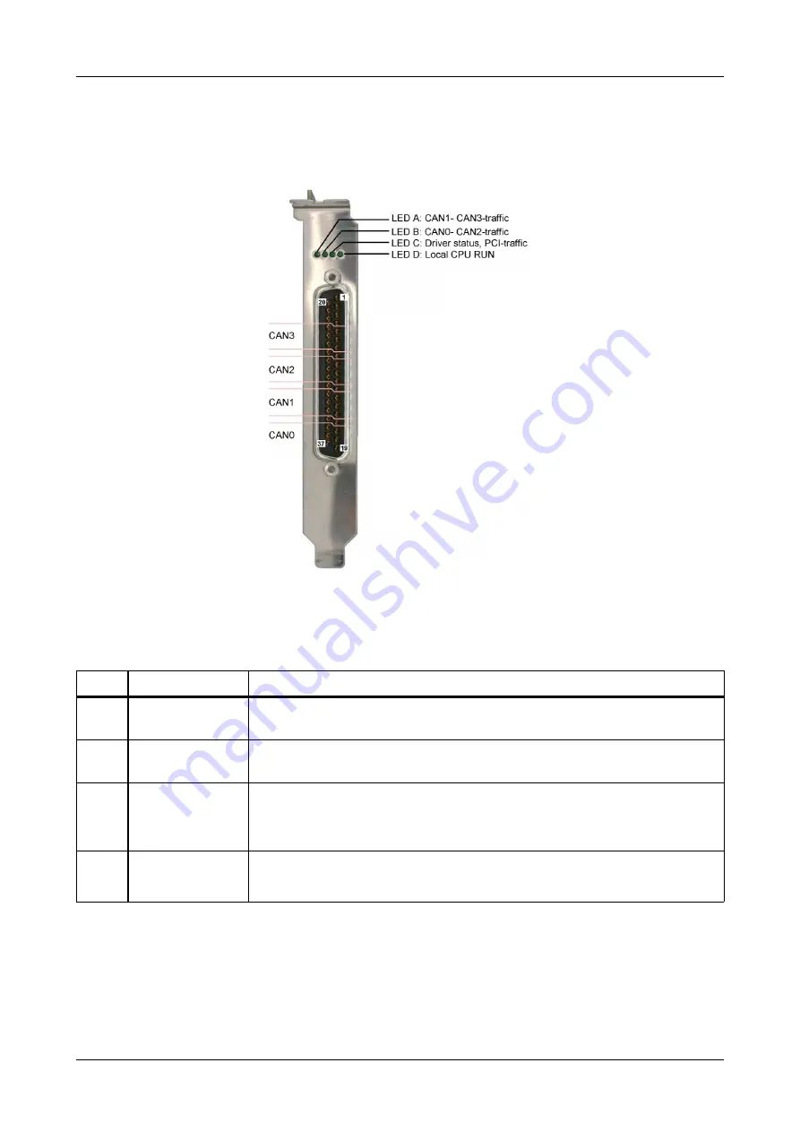
Four CAN nets can be connected to the CAN-PCI/405-B4 card via the 37-pole DSUB panel
connector in the slot bracket.
Figure 3:
LEDs and connector position
LED
Function
Indication of the LED (LED on)
A
CAN1-, CAN3-
traffic
CAN-frames are being received or transmitted on CAN1 and/or CAN3
B
CAN0-, CAN2-
traffic
CAN-frames are being received or transmitted on CAN0 and/or CAN2
C
Driver status/
PCI traffic
LED off:
LED on:
LED
flickering:
No driver loaded
Driver loaded
Communication with CAN-board
D
Local CPU RUN
Local CPU is in RUN status
(LED lights at every access to the SDRAM, therefore the LED can be
blinking or permanently on in normal operation)
Table 1:
Name and indication of the LEDs
Page 10 of 29
Hardware Manual • Doc. No.: C.2041.21 / Rev. 1.2
CAN-PCI/405-B4