background image

Order Information 


CPCI-CAN/200


 Hardware Manual Doc.-Nr.: C.2035.21/ Rev. 2.2 

Page 31 of 31 


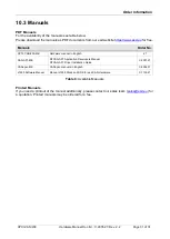
PDF Manuals 

For the availability of the manuals see table below. 
Please download the manuals as PDF documents from our esd website 

https://www.esd.eu

 for free. 


Manuals 

Order No. 

CPCI-CAN/200-ME


Hardware manual in English 


.21


CAN-API-ME


NTCAN-API: Application Developers Manual


NTCAN-API: Driver Installation Guide


C.2001.21


CANopen-ME


CANopen manuals in English 


C.2002.21


J1939 Software Manual 


Manual J1939 Stack and SDK for esd CAN Hardware


C.1130.21


Table 8:

 Available Manuals 


Printed Manuals 

If you need a printout of the manual additionally, please contact our sales team (

[email protected]

) for 

a quotation. Printed manuals may be ordered for a fee. 
 

10.3  Manuals 

Содержание C.2035.02

Страница 1: ...CPCI CAN 200 Hardware Manual Doc Nr C 2035 21 Rev 2 2 Page 1 of 31 CPCI CAN 200 CompactPCI CAN Interface Hardware Manual to Product C 2035 02 C 2035 04 C 2035 07 ...

Страница 2: ...ountries All other trademarks product names company names or company logos used in this manual are reserved by their respective owners Notes The information in this document has been carefully checked and is believed to be entirely reliable esd electronics makes no warranty of any kind with regard to the material in this document and assumes no responsibility for any errors that may appear in this...

Страница 3: ...es versus previous version Date 2 1 Order information revised wiring hints revised editorial revision 2014 09 25 2 2 Classification of Warning Messages and Safety Instructions inserted Instructions revised 2021 07 21 1 1 Description of CPCI CAN 200 2 T version inserted 2 3 1 Note on availability of CAN 1 inserted 4 Safety information revised 5 1 Description of Connectors and temperature range revi...

Страница 4: ...so include a warning relating to property damage DANGER Danger statements indicate a hazardous situation which if not avoided will result in death or serious injury WARNING Warning statements indicate a hazardous situation that if not avoided could result in death or serious injury CAUTION Caution statements indicate a hazardous situation that if not avoided could result in minor or moderate injur...

Страница 5: ... use Always allow adequate ventilation around the CPCI CAN 200 and use care when handling Do not operate the CPCI CAN 200 adjacent to heat sources and do not expose it to unnecessary thermal radiation Ensure an ambient temperature as specified in the technical data DANGER Hazardous Voltage Risk of electric shock due to unintentional contact with uninsulated live parts with high voltages inside of ...

Страница 6: ...d of safety instructions and warnings The CPCI CAN 200 is intended for installation in a CompactPCI system The operation of the CPCI CAN 200 in hazardous areas or areas exposed to potentially explosive materials is not permitted The operation of the CPCI CAN 200 for medical purposes is prohibited Service Note The CPCI CAN 200 does not contain any parts that require maintenance by the user The CPCI...

Страница 7: ...Twisted Pair Cable 20 7 2 1 General Rules 20 7 2 2 Device Cabling 21 7 2 3 Branching 21 7 2 4 Termination 21 7 3 Light Industrial Environment Single Twisted Pair Cable 22 7 3 1 General Rules 22 7 3 2 Cabling 23 7 3 3 Branching 23 7 3 4 Termination 23 7 4 Electrical Grounding 24 7 5 Bus Length 24 7 6 Examples for CAN Cables 25 7 6 1 Cable for Light Industrial Environment Applications Two Wire 25 7 ...

Страница 8: ...e 8 Available Manuals 31 List of Figures Figure 1 Block circuit diagram 9 Figure 2 PCB top view of CPCI CAN 200 2 11 Figure 3 Connectors and LEDs 12 Figure 4 CAN wiring for heavy industrial environment 20 Figure 5 Example of proper wiring with single shielded double twisted pair cables 21 Figure 6 CAN wiring for light industrial environment 22 Figure 7 Example for proper wiring with single shielde...

Страница 9: ... 2 T Data security and consistency are guaranteed up to 1 Mbit s The ISO 11898 compliant CAN interface allows a maximum data transfer rate of 1 Mbit s Among many other features of CAN interfaces the bit rate can be set by software The CAN interface is electrically isolated from the other potentials by means of optocouplers and DC DC converters The CPCI CAN 200 2 T version is designed for the exten...

Страница 10: ...bbreviation Term API Application Programming Interface CAN Controller Area Network CPU Central Processing Unit CiA CAN in Automation HW Hardware I O Input Output LSB Least Significant Bit MSB Most Significant Bit n a not applicable OS Operating System SDK Software Development Kit 1 2 Glossary ...

Страница 11: ...CB View with Connectors Figure 2 PCB top view of CPCI CAN 200 2 INFORMATION The interface CAN1 is not equipped on CPCI CAN 200 1 NOTICE Read chapter Hardware Installation on page 13 before you start with the installation of the hardware See also page 18 for signal assignment of the CAN connectors ...

Страница 12: ...Description 1A green not implemented n a not implemented 1B green IRQ CAN 1 off Interrupt of CAN controller of CAN1 inactive on Interrupt of CAN controller of CAN1 active 1C green IRQ CAN 0 off Interrupt of CAN controller of CAN0 inactive on Interrupt of CAN controller of CAN0 active PWR green Power off Power supply off on Power supply on Table 1 Description of LEDs 3 1 Position of the LEDs 3 2 LE...

Страница 13: ...r clothes might be electrostatically charged as well Procedure 1 Switch off your CompactPCI system and all connected peripheral devices monitor printer etc 2 Discharge your body as described above 3 Disconnect the system from the mains Make sure that no risk arises from the system into which the CPCI CAN 200 shall be inserted DANGER Hazardous Voltage Risk of electric shock due to unintentional con...

Страница 14: ...ected to earth at exactly one point in the CAN network For details please read chapter Correct Wiring Electrically Isolated CAN Networks from page 19 The first CAN interface CAN network 0 is connected via the DSUB connector X301 and the second CAN interface CAN network 1 is connected via the DSUB connector X311 9 Connect the system to mains again mains connector or safety fuse 10 Switch on the sys...

Страница 15: ... strip ISP programming Temperature range CPCI CAN 200 1 CPCI CAN 200 2 0 50 C CPCI CAN 200 2 T 40 85 C Humidity max 90 non condensing Dimensions 3U 4HP CompactPCI board 100 mm x 160 mm without connectors Weight 170 g Table 2 General Data of the module Number of CAN interfaces CPCI CAN 200 1 1x CAN CPCI CAN 200 2 2x CAN CAN controller SJA1000 CAN protocol according to ISO 11898 1 Physical CAN Layer...

Страница 16: ...CI Local Bus Specification 2 1 PCI data address bus 32 bit Controller PLX 9030 Interrupt interrupt signal A Board dimension according to CompactPCI Specification Rev 1 0 Connectors Connector coding Universal Board not keyed 3 3 V or 5 V signalling voltage Table 4 Data of the CompactPCI interface 5 3 CompactPCI Bus ...

Страница 17: ...d Firmware Update Installation Guide esd order No C 2001 21 CAN Tools esd offers additional free of charge tools which support efficient setup and analysis of CAN applications and networks The CAN Tools are operational with all esd PC CAN interfaces e g PCIe USB EtherCAN 2 The following CAN Tools are available CANreal Display and record of CAN message frames CANplot Graphical display of CAN data C...

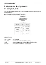
Страница 18: ...ector 9 pin DSUB connector pin contacts Pin Position Pin Assignment Signal Pin Signal 1 Reserved CAN_GND 6 2 CAN_L CAN_H 7 3 CAN_GND Reserved 8 4 Reserved Reserved 9 5 Shield Signal Description CAN_L CAN_H CAN signal lines CAN_GND reference potential of the local CAN physical layer Shield shielding connected with the case of the 9 pin DSUB connector Reserved reserved for future applications do not...

Страница 19: ...f CAN for applications outside the original ISO 11898 They have made system level tradeoffs for data rate cable length and parasitic loading of the bus However for CAN network design margin must be given for signal loss across the complete system and cabling parasitic loadings network imbalances ground offsets against earth potential and signal integrity Therefore the practical maximum number of n...

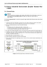
Страница 20: ... wire CAN cable Connect two twisted wires to the data signals CAN_H CAN_L and the other two twisted wires to the reference potential CAN_GND and the cable shield to functional earth FE at least at one point 3 The reference potential CAN_GND has to be connected to the functional earth FE at exactly one point 4 A CAN bus line must not branch exception short cable stubs and has to be terminated with ...

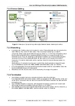
Страница 21: ...he CAN T Connector Manual order no C 1311 21 Alternatively a T connector can be used in which the shield potential is looped through e g the DSUB9 connector from ERNI ERBIC CAN BUS MAX order no 154039 If a mixed application of single twisted and double twisted cables is unavoidable take care that the CAN_GND line is not interrupted Deviations from the bus structure can be realized by the usage of ...

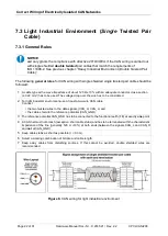
Страница 22: ...he wire has to be considered 2 For light industrial environment use at least a two wire CAN cable Connect the two twisted wires to the data signals CAN_H CAN_L and the cable shield to the reference potential CAN_GND 3 The reference potential CAN_GND has to be connected to the functional earth FE at exactly one point 4 A CAN net must not branch exception short cable stubs and has to be terminated w...

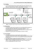
Страница 23: ...or Order No C 1311 03 If a mixed application of single twisted and double twisted cables is unavoidable take care that the CAN_GND line is not interrupted Deviations from the bus structure can be realized by the usage of repeaters 7 3 4 Termination A termination resistor has to be connected at both ends of the CAN bus If an integrated CAN termination resistor which is equipped at the CAN interface...

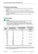
Страница 24: ... standard values of the cross section depending on the cable length are described in the CiA recommendation CiA 303 1 see CiA 303 CANopen Recommendation Part 1 Cabling and connector pin assignment Version 1 9 0 Table 2 Bit Rate kbit s Theoretical values of reachable wire length with esd interface lmax m CiA recommendations 07 95 for reachable wire lengths lmin m Standard values of the cross sectio...

Страница 25: ...bH Äußerer Eichwald 74535 Mainhardt Germany www concab de e g BUS PVC C 1x 2x 0 22 mm Order No 93 022 016 UL appr BUS Schleppflex PUR C 1x 2x 0 25 mm Order No 94 025 016 UL appr 7 6 2 Cable for Heavy Industrial Environment Applications Four Wire Manufacturer Cable Type U I LAPP GmbH Schulze Delitzsch Straße 25 70565 Stuttgart Germany www lappkabel com e g UNITRONIC BUS CAN UL CSA 2x 2x 0 22 UL CSA...

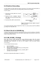
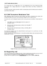
Страница 26: ...pedance are equal these reflections are avoided This test measures the series resistance of the CAN data pair conductors and the attached terminating resistors To test it please 1 Turn off all power supplies of the attached CAN nodes 2 Measure the DC resistance between CAN_H and CAN_L at one end of the network see figure above The measured value should be between 50 Ω and 70 Ω If the value is belo...

Страница 27: ... to transmit data if there is a short circuit between CAN_GND and CAN_L but generally the error rate will increase strongly Make sure that there is no short circuit between CAN_GND and CAN_L Each node contains a CAN transceiver that outputs differential signals When the network communication is idle the CAN_H and CAN_L voltages are approximately 2 5 V measured to CAN_GND Faulty transceivers can ca...

Страница 28: ...ance measuring device and 1 Switch off the node and disconnect it from the network see figure below 2 Measure the DC resistance between CAN_H and CAN_GND see figure below 3 Measure the DC resistance between CAN_L and CAN_GND see figure below The measured resistance has to be about 500 kΩ for each signal If it is much lower the CAN transceiver it is probably faulty Another indication for a faulty t...

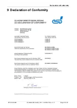
Страница 29: ...Declaration of Conformity CPCI CAN 200 Hardware Manual Doc Nr C 2035 21 Rev 2 2 Page 29 of 31 9 Declaration of Conformity ...

Страница 30: ...or QNX 4 x and 6 x C 1101 32 CAN DRV LCD CDROM Lizenz RTX Object Licence and CD ROM for RTX C 1101 35 CAN DRV LCD CDROM Lizenz VxWorks Object Licence and CD ROM for VxWorks 5 x and 6 x C 1101 55 CAN DRV LCD On Time RTOS 32 Object Licence and CD ROM for On Time RTOS 32 C 1101 45 Higher Layer Protocols including CD ROM Classical CAN Applications only CANopen LCD Windows Linux CANopen Object Driver L...

Страница 31: ...N 200 ME Hardware manual in English 21 CAN API ME NTCAN API Application Developers Manual NTCAN API Driver Installation Guide C 2001 21 CANopen ME CANopen manuals in English C 2002 21 J1939 Software Manual Manual J1939 Stack and SDK for esd CAN Hardware C 1130 21 Table 8 Available Manuals Printed Manuals If you need a printout of the manual additionally please contact our sales team sales esd eu f...

Отзывы: