Hardware Installation
Page 14 of 31
Hardware Manual Doc.-Nr.: C.2035.21 / Rev. 2.2
CPCI-CAN/200
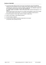
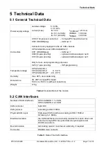
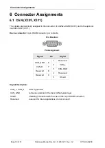
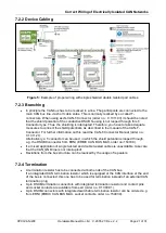
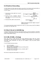
8. Connect the CAN interfaces via the connectors in the front panel of the CPCI-CAN/200:
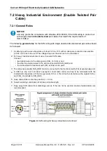
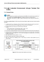
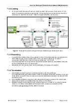
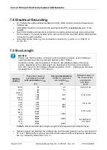
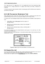
Please note that the CAN bus must be terminated at both ends! esd offers special T-connectors
and termination connectors for external termination. Additionally, the CAN_GND signal must
be connected to earth at exactly one point in the CAN network.
For details, please read chapter
“
Correct Wiring Electrically Isolated CAN Networks
”
from
page 19.
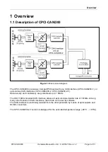
The first CAN interface (CAN network 0) is connected via the DSUB-connector (X301) and the
second CAN interface (CAN network 1) is connected via the DSUB-connector (X311).
9. Connect the system to mains again (mains connector or safety fuse).
10. Switch on the system and the peripheral devices.
11. End of hardware installation.
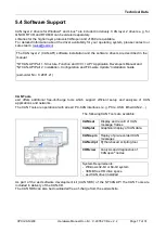
12. Continue with the software installation as described in the manual
“NTCAN-API: Driver Installation Guide”.


