Correct Wiring of Electrically Isolated CAN Networks
Page 24 of 31
Hardware Manual Doc.-Nr.: C.2035.21 / Rev. 2.2
CPCI-CAN/200
●
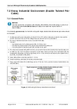
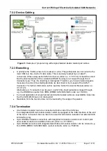
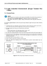
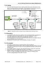
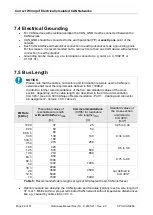
For CAN devices with electrical isolation the CAN_GND must be connected between the
CAN devices.
●
CAN_GND should be connected to the earth potential (FE) at
exactly one
point of the
network.
●
Each
CAN interface with electrical connection to earth potential
acts as a grounding point.
For this reason, it is recommended not to connect more than one
CAN device with electrical
connection to earth potential.
●
Grounding can be made e.g. at a termination connector (e.g. order no. C.1302.01 or
C.1301.01).
NOTICE
Please note that the cables, connectors and termination resistors used in CANopen
networks shall meet the requirements defined in ISO 11898-2.
In addition, further recommendations of the CiA, like standard values of the cross
section, depending on the cable length, are described in the CiA recommendation
CiA
303-1 (see CiA 303 CANopen Recommendation - Part 1:
„
Cabling and connector
pin assignment“, Version 1.9.0, Table 2).
Bit Rate
[kbit/s]
Theoretical values of
reachable wire length
with esd interface
lmax
[m]
CiA recommendations
(07/95) for reachable
wire lengths lmin
[m]
Standard values of
the cross-section
according to
CiA 303-1
[mm²]
1000
37
25
0.25 to 0.34
800
666.
6
500
333.
3
250
59
80
130
180
270
50
-
100
-
250
0.34 to 0.6
166
125
420
570
-
500
0.5 to 0.6
100
83.
3
66.
6
50
710
850
1000
1400
650
-
-
1000
0.75 to 0.8
33.
3
20
12.5
10
2000
3600
5400
7300
-
2500
-
5000
not defined in
CiA 303-1
Table 5:
Recommended cable lengths at typical bit rates (with esd-CAN interfaces)
●
Optical couplers are delaying the CAN signals. esd modules typically reach a wire length of
37 m at 1 Mbit/s within a proper terminated CAN network without impedance disturbances
like e.g. caused by cable stubs > 0.3 m.
7.4 Electrical Grounding
7.5 Bus Length

