EScale Seafire Скачать руководство пользователя страница 26

26

Seafire Instruction Manual

25

Cut.

Epoxy.

Содержание Seafire

Страница 1: ...sq in 49 3sq dm Weight 8 8lbs 4 0kg Length 50 4in 128cm Engine 0 75 0 91cu in 2 stroke 0 91 1 00cu in 4 stroke Radio 6 channels with 8 servos Retracts landing gear included Graphics and specifications may change without notice Celebrating over 100 years of Naval Aviation ...

Страница 2: ...ldings power lines water or trees Only fly in bright sunny conditions where wind speed does not exceed 15mph Guarantee warranty J Perkins Distribution Ltd guarantee this product to be free of manufacturing and assembly defects for a period of one year from time of purchase and Model Engines Pty Ltd for 30 days This does not affect your statutory rights This warranty is not valid for any damage or ...

Страница 3: ...ad this manual thoroughly before starting assembly of your EScale Seafire Use the parts listing below to identify all parts KIT CONTENTS 1 2 3 4 4 5 6 7 8 9 9 9 9 9 1 Fuselage with canopy 2 Left wing panel 3 Right wing panel 4 Tail set 5 Aluminium wing tube 6 Fiberglass cowl 7 Retracts landing gear 8 EP conversion pack 9 Hardware bag included ADDITIONAL ITEMS REQUIRED 0 75 0 91 2 stroke or 0 91 1 ...

Страница 4: ...e steps that follow using a high quality thin C A glue 2 Remove each hinge from the wing panel and aileron and place a T pin in the center of each hinge Slide each hinge into the aileron until the T pin is snug against the aileron This will help ensure an equal amount of hinge is on either side of the hinge line when the aileron is mounted to the wing panel HINGING THE AILERONS Note 1 Carefully re...

Страница 5: ...he opposite side Apply thin C A glue to each hinge making sure that the C A penetrates into both the aileron and wing panel Work the aileron up and down several times to work in the hinges and check for proper movement Note HINGING THE ELEVATOR Glue the elevator hinges in place using the same techniques used to hinge the ailerons 4 Deflect the aileron and completely saturate each hinge with thin C...

Страница 6: ...to install the control horns for the ailerons 2 Position the control horn on the bottom of the aileron You will see pre drill hole 3mm for the horn mounting screw on the aileron 3 Place epoxy into hole This will harden the threads and prevent the screws from pulling loose 4 Thread a control horn end with aluminium washer lock nut until the top edge of the end is 18mm from the base of the horn as s...

Страница 7: ...tall the elevator control horn using the same method as the aileron control horns INSTALL ELEVATOR CONTROL HORN CONTROLHORN M3 SCREW M3 lock nut ALUMINIUMWASHER 18mm ALUMINIUM WASHER Epoxy Epoxy Flap Aluminium Washer CONTROL HORN M3 SCREW M3 LOCK NUT Epoxy Aluminium Washer Flap 2 sets 3x35mm 3mm ...

Страница 8: ...mm Epoxy Rudder INSTALL RUDDER CONTROL HORN 1 sets 3x50mm Elevator control horn 3mm Repeat steps to install the rudder control horn as same as steps done for ailerons Aluminium Washer CONTROL HORN M3 SCREW M3 LOCK NUT Epoxy Aluminium Washer Elevator Horizontal Stabiliser 18mm Epoxy Elevator Horizontal Stabiliser Rudder control horn ...

Страница 9: ...the screws to help prevent them from vibrating loose 4x30mm Thread locker glue 1 Using a modelling knife carefully cut off the rear portion of one of the 3 nylon tubes leaving 1 2 protruding from the rear of the stopper This will be the fuel pick up tube INSTALLING THE STOPPER ASSEMBLY 2 Using a modelling knife cut one length of silicon fuel line Connect one end of the line to the weighted fuel pi...

Страница 10: ...5 With the stopper assembly in place the weighted pick up should rest away from the rear of the tank and move freely inside the tank The top of the vent tube should rest just below the top of the tank It should not touch the top of the tank 6 When satisfied with the alignment of the stopper assembly tighten the 3 x 20mm machine screw until the rubber stopper ex pands and seals the tank opening Do ...

Страница 11: ...er servo arm 2 Install the rubber grommets and brass collets onto the throttle servo Test fit the servo into the aileron servo mount 3 Secure the servos with the screws pro vided with your radio system Because the size of servos differ you may need to adjust the size of the precut open ing in the mount The notch in the sides of the mount allow the servo lead to pass through 3 32 Hole INSTALLING TH...

Страница 12: ...ll a small indentation in the mount for the engine mounting screw 3 Use a drill to drill the four holes in the engine mount rails 4 On the fire wall has the location for the throttle pusshrod tube pre drill 1 Position the engine with the drive washer 145mm forward of the firewall as shown 4 5mm Pushrod tube hole 4mm 4 2mm ...

Страница 13: ... vibrate loose COWLING Trim and cut 1 Slide the fiberglass cowl over the engine and line up the back edge of the cowl with the marks you made on the fuselage then trim and cut as shown Machine screw M4x30mm Pushrod wire Trim and cut 7 Slide the throttle pushrod wire into the tube Position the engine between the mounts Use four M4x30mm machine screws to secure the engine to the mount as shown 5 Sli...

Страница 14: ...rews 2 While keeping the back edge of the cowl flush with the marks align the front of the cowl with the crankshaft of the engine The front of the cowl should be positioned so the crankshaft is in nearly the middle of the cowl opening Use the spinner backplate as a guide Hold the cowl firmly in place using pieces of masking tape Trim and cut ELECTRIC POWER CONVERSION 1 Locate the items necessary t...

Страница 15: ...n Manual SEAFIRE 14 3 Attach the motor to the front of the electric motor box using four 3mm blind nut four M3x15mm hex head bolt s to secure the motor Please see picture shown Epoxy 110mm 4mm 4mm Balsa stick Epoxy M3x15mm ...

Страница 16: ...to the side of the motor box using two sided tape and tie wraps Connect the appropriate leads from the speed control to the motor Make sure the leads will not interfere with the operation of the motor INSTALLING THE SPINNER Install the spinner backplate propeller and spinner cone The propeller should not touch any part of the spinner cone If it does use a sharp modelling knife and carefully trim a...

Страница 17: ...ply 1 2 drops of thin C A to each of the mounting tabs Allow the C A to cure without using accelerator INSTALLING THE AILERON FLAPSERVOS Servos Small weight Thread String Small weight 1 Using a small weight Weighted fuel pick up works well and string feed the string through the wing as indicated 2 Place the servo between the mounting blocks and space it from the hatch Use a pencil to mark the moun...

Страница 18: ...ng root Remove the string from the wing at the servo location and use the tape to attach it to the servo extension lead Pull the lead through the wing and remove the string 9 Set the aileron hatch in place and use a Phillips screw driver to install it with four wood screws AILERON PUSHROD HORN INST ALLATION Mark Pen ...

Страница 19: ... Snap keeper Servo arm 3 Connect the linkage as shown and secure the control wire with a snap keeper 8mm Snap keeper M2 lock nut Metal clevis 1 Mark the control wire where it crosses the servo arm hole Bend at the mark 2 Make a 90 degree bend at the mark and cut off the excess wire leaving 8mm past the bend Cut 8mm ...

Страница 20: ...TALLING THE FLAP SERVO M2 lock nut Wing Flap Repeat the procedure for the aileron servo WING ASSEMBLY Masking tape Epoxy Masking tape Epoxy Epoxy 1 Epoxy 1 SERVO GEAR INSTALLATION Servo for retractable only Metal connector Servo arm 25mm ...

Страница 21: ...21 Seafire Instruction Manual SEAFIRE 20 Servo arm Loctile secure Adjustable servo connector 25mm Wing bottom Electric wire INSTALLING RETRACTABLE LANDING GEAR 1 2 3 4 5 6 7 8 1 5mm ...

Страница 22: ...22 Seafire Instruction Manual 21 PUSHROD INSTALLATION 220mm 200mm Cut M2 lock nut M2 clevis 4 2mm 2mm 1 Epoxy 4 Epoxy 3 2 1 ...

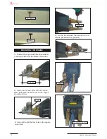
Страница 23: ...23 Seafire Instruction Manual SEAFIRE 22 Cut M3x25mm 8 5 7 5 7 6 9 9 7 7 ...

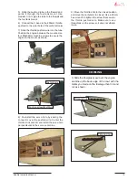
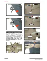
Страница 24: ...24 Seafire Instruction Manual 23 M3x25mm 8 1 11 Epoxy 9 8 35mm 40mm 10 11 10 11 ...

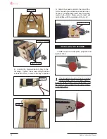
Страница 25: ...25 Seafire Instruction Manual Close Position 12mm Open Position servo arm servo arm ...

Страница 26: ...26 Seafire Instruction Manual 25 Cut Epoxy ...

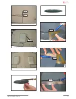
Страница 27: ...27 Seafire Instruction Manual SEAFIRE 26 C A glue 30mm 12mm 48mm 30mm 155mm ...

Страница 28: ... and the rear of the stabiliser with the centre of the fu selage When that is aligned hold the stabi liser in that position using T pins or masking tape Align the horizontal stabiliser with the wing When viewed from the rear the hori zontal stabiliser should be level with the wing If it is not level use sandpaper and sand down the high side of the stabiliser mounting plat form until the proper ali...

Страница 29: ...as fully cured re move the masking tape or T pins used to hold the stabiliser in place Carefully inspect the glue joints Use more epoxy to fill in any gaps that may exist that were not filled previously and clean up the excess using a paper towel and rubbing alcohol 1 Using a modelling knife remove the covering from over the precut hinge slot cut into the lower rear portion of the fuselage When cu...

Страница 30: ... the vertical sta biliser mounting area Apply epoxy to the bot tom and top edges of the filler blockand to the lower hinge also Set the stabiliser in place and realign Double check all of your measure ments once more before the epoxy cures Hold the stabiliser in place with T pins or masking tape and remove any excess epoxy using a paper towel and rubbing alcohol Allow the ep oxy to fully cure befo...

Страница 31: ...dder pushrods assembly as pictures below 3 Thread one clevis and M2 lock nut on to each elevator control rod Thread the horns on until they are flush with the ends of the con trol rods 604mm Cut ELEVATOR PUSHROD HORN INSTALLATION 1 Install the elevator control horn using the same method as with the aileron control horns 2 Position the elevator control horn on the both side of elevator C A glue ...

Страница 32: ...32 Seafire Instruction Manual 31 RUDDER PUSHROD HORN INSTALLATION 8mm 8mm 8mm 8mm Pen 8mm M2 lock nut M2 clevis Control horn M2 lock nut Metal clevis Elevator pushrod Rudder pushrod Pen ...

Страница 33: ...os arm to servos Notice the posi tion of the servo arms on the servos See picture below MOUNTING THE TAIL WHEEL Locate items necessary to inst all tail gear Rudder pushrod Elevator pushrod A C A glue Elevator control horn Rudder control horn Elevator pushrod A C A glue A 8mm Cut ...

Страница 34: ...s and dust Position decal on the model where desired using the photos on the box to aid in their location 2 If all the decals are not precut please use scissors or a sharp hobby knife to cut the decals from the sheet Please be certain the model is clean and free from oily fingerprints and dust Position decal on the model where desired using the photos on the box to aid in their location ...

Страница 35: ...he antenna is removeable so you can install it at the flying field to prevent damage in trans porting A B A INSTALLING ANTENNA AND THE RECEIVER 1 Plug the five servo leads and the switch lead into the receiver Plug the battery pack lead into the switch also 3 Route the antenna in the antenna tube inside the fuselage and secure it to the bottom of fuselage using a plastic tape 2 Wrap the receiver a...

Страница 36: ...attach the wing to the fuselage Make sure the distance between a point centered at the rear of the fuselage and each wing tip The measurement will be equal if the wing is aligned correctly If the measure ment is not the same slightly the hole for the wing bolts until an equal measurement is achieved CENTRE OF GRAVITY A A B 1 5mm M3x10mm Wing bolt M3x10mm ...

Страница 37: ...ows listed BELOW We have listed control throws for both Low Rate initial test flying sport flying and High Rate aerobatic flying 2 Turn on the radio system and with the trim tabs on the transmitter in neutral center the control surfaces by making adjustments to the clevises or adjustable servo connectors The servo arms should be centered also 3 When the elevator rudder and aileron control surfaces...

Страница 38: ...38 Seafire Instruction Manual ...

Страница 39: ...39 Seafire Instruction Manual ...

Страница 40: ...Australasia agents Model Engines Melbourne Australia www modelengines com au European agents J Perkins Distribution Lenham England www jperkinsdistribution co uk ...

Отзывы: