


11
Seafire Instruction Manual
SEAFIRE
.
10
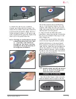
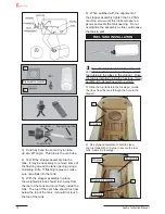
Blow through one of the lines to en-
sure the fuel lines have not become kinked
inside the fuel tank compartment. Air
should flow through easily.
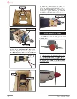
INSTALLING THE FUSELAGE SER VOS
Throttle servo.
Elevator servo.
Rudder servo.
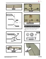
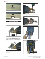
THROTTLE SERVO ARM INSTALLATION
Install adjustable servo connector in the servo
arm as same as picture below:
Adjustable Servo
connector.
Servo arm.
Loctite secure.
1 PCS.
Throttle servo arm.
Elevator servo arm.
Rudder servo arm.
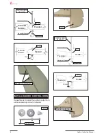
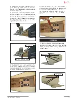
2) Install the rubber grommets and brass
collets onto the throttle servo. Test fit the servo
into the aileron servo mount.
3) Secure the servos with the screws pro-
vided with your radio system.
Because the size of servos differ , you
may need to adjust the size of the precut open-
ing in the mount. The notch in the sides of the
mount allow the servo lead to pass through.
3/ 32” Hole.
INSTALLING THE SWITCH
Install the switch into the precut hole in the
side, in the fuselage.
Vent tube.
Fuel pick up tube.
Fuel fill tube.
9) Connect the lines from the tank to the
engine and muffler. The vent line will connect
to the muffler and the line from the clunk to the
carburettor.
Содержание Seafire
Страница 23: ...23 Seafire Instruction Manual SEAFIRE 22 Cut M3x25mm 8 5 7 5 7 6 9 9 7 7 ...
Страница 24: ...24 Seafire Instruction Manual 23 M3x25mm 8 1 11 Epoxy 9 8 35mm 40mm 10 11 10 11 ...
Страница 25: ...25 Seafire Instruction Manual Close Position 12mm Open Position servo arm servo arm ...
Страница 26: ...26 Seafire Instruction Manual 25 Cut Epoxy ...
Страница 27: ...27 Seafire Instruction Manual SEAFIRE 26 C A glue 30mm 12mm 48mm 30mm 155mm ...
Страница 38: ...38 Seafire Instruction Manual ...
Страница 39: ...39 Seafire Instruction Manual ...


