4 (32)
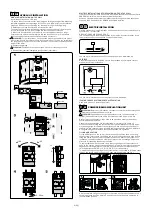
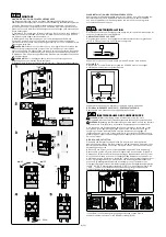
MULTIPLE INSTALLATIONS OF CIRCULATION UNITS ON THE WALL
If more than one Circulation Unit should be used we recommend the use of Serie
ESBE GMA manifold, with or without hydraulic separator.
When no storage tank or other components performing a hydraulic separation
are used, then manifold series GMA2XX should be installed.
.
ELECTRIC INSTALLATION
Electric connection of the Circulation Unit depends both on the circulation pump,
actuator and /or controller.
CIRCULATION PUMP 230 VAC, 50HZ:
The circulation pump should be preceded by a multi-pole contact breaker in the
fixed installation. Earth-connection should not be broken.
L
N
You find more information about the circulation pump on www.esbe.eu.
ACTUATOR:
Actuators supplied with 230 VAC should be preceded by a mulitipole contact
breaker in the fixed installation.
M
You find more information about the actuator on www.esbe.eu.
IF USING LARGER SYSTEMS/CENTRAL REGULATING
Read each product´s instruction manual.
COMMISSIONING CIRCULATION UNIT
WARNING!
Before any intervention disconnect the electric mains through the
external mounted switch and depressurise!
WARNING!
Depending on the operating status of the circulation pump or
system (fluid temperature), the entire Circulation Unit can become very hot.
Both primary and secondary loops have to be washed in order to remove any
possible mounting residuals.
Check that all connections are fully tightened: it´s important to check all
connections before filling the system in order to avoid leakages or sprays which
may be dangerous for the electric components. Open all shut-off valves and fill
the primary and secondary loop following the instructions for the tank, boiler etc.
During the filling phase recheck that all connections are tightened.
FILLING AND VENTING
Fill the buffer tank and the primary loop with an appropriated liquid, according
to the system instructions, respecting the limits of the components used. While
filling the device, open any vents situated in the circuit. Watch the system until
it reaches its correct operation condition. If pressure is not enough, adjust the
pressure by repeating the above procedure.
To avoid problems with cavitation, fill up the system to get sufficient pressure
head on the suction side of the circulation pump. The minimum pressure needed
depends on the temperature of the fluid. Recommended min pressure head at
fluid temperatures 50/95/110°C is 0,5/4,5/11 m respectively.
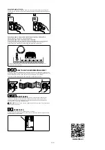
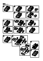
To make the filling and venting of the system easier it´s possible to force the check
valve on the return side of the unit, to an open position (default), see Fig. 1.
After a complete filling and venting, turn the screw on the check valve back to it´s
normal operating position, picture 2 and set the circulation pump operation to
recommended position.
HYDRAULIC INSTALLATION
SINGULAR INSTALLATION ON THE WALL
Install the appliance on a solid wall.
1. Choose the correct position for the piping and drilling by usage of the Mounting
template supplied with the package. Drill the holes in the wall for your installation
purposes. Take care not to damage any electrical wiring or existing piping.
2. Detach parts of the Circulation Unit's insulation shell.
The actuator/controller might be dismounted from the valve to give more space
for the installation tools. Do not change the shaft position of the valve.
3. Mount the Circulation Unit on the wall with the supplied screws and plugs.
Ensure that the pipes are completely in line and lock them firmly.
*Please note
that to achive best performance there should be no tilt at all.
WARNING!
For all installations, verify that the plugs are suitable for the kind of
wall chosen. Otherwise replace them with a special model. To value the suitability of
the plugs please consider the structure of the wall, all the units connected and the
weight of the water.
4. Connect the pipings.
WARNING!
Equipment might be damaged when incorrect usage of tools.
5. Remount the insulation shell parts (and actuator/controller).
GDF100
180˚
>
180˚
>
40 - 50 Nm
GRF100
GFF100
0º
*


