


14
Figure 5 - Threading the Wire
3.4.3 WELDING WIRE SPOOL INSTALLATION
As with any work area, make sure safety glasses with
side shields are worn when handling or changing wire
or clipping wire off at the spool or at the end of the
torch. Hold onto the wire coming off the spool with
one hand before clipping. Serious eye injury can re-
sult due to the resilience of the wire which can quickly
unravel, or a cut wire end which may shoot across the
room.
Install a spool of welding wire on the spindle as follows:
A. Unscrew red plastic nut.
B. Place wire spool on the spindle to rotate counter-
clockwise (wire feeds off of the top) as wire is un-
wound; spindle brake pin must engage hole in spool.
C. Spool spacer is used when running a 10# Spool of
Wire. Place wire on first, followed by spacer, and then
plastic nut.
D. Replace the locking nut.
3.4.4 THREADING WELDING WIRE
A. Turn off power switch.
B. Release pressure drive roll assembly. Check that
proper wire diameter grooves are in the inner position.
Before threading welding wire, make sure chisel point
and burrs have been removed from wire end to pre-
vent wire from jamming in gun or
liner.
SECTION 3
INSTALLATION
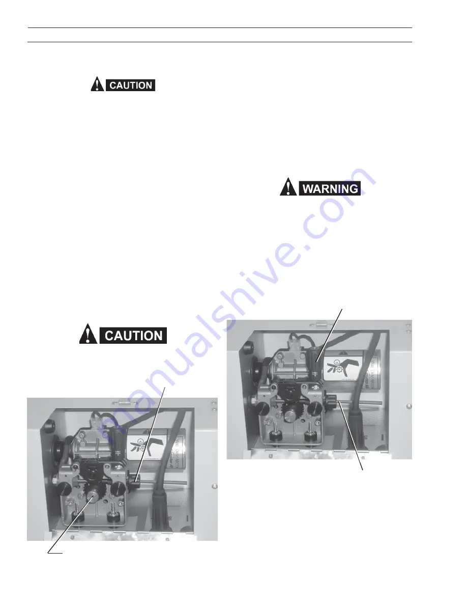
Figure 4 - Wire Feeder Mechanism
C. Feed the wire from the spool through the inlet guide,
across the drive roll grooves into the outlet guide and
cc connection tube.
To ensure proper wire feeding, it is important that the
wire be kept clean and that the drive rolls be periodically
cleaned of any chips or scale that might be carried into
the gun liner.
D. Lower pressure roll assembly and secure. Turn the
power “on” and feed wire through to gun tip using the
gun trigger to start wire feeding.
When the power switch is on, and gun trigger is de-
pressed, the electrode wire becomes electrically hot,
and the wire drive rolls will rotate.
3.4.5 SPOOL BRAKE DRAG ADJUSTMENT
Spool brake disc friction should provide enough drag to
keep the wire spool from spinning freely after wire feed
stops. If adjustment is required, turn the adjusting screw
inside the spindle housing clockwise to increase drag or
counterclockwise to decrease it. Drag should be just
enough to limit wire overrun.
Threading the wire through
the inlet guide
Pressure Release Lever
Feed Roll Release Screw
Inlet Guide
3.5 CONNECTION OF SHIELDING GAS SUPPLY
3.5.1 R-33-FM-580 Regulator (OPTIONAL)
The R-33-FM-580 regulator is an adjustable regulator de-
signed for use with Argon, Helium, and C-25 (75% Ar-
gon/25% CO
2
) gas service. Table 2 table provides the
recommended flow ranges for the R-33-FM-580 regula-
tor.
Содержание MultiMaster 160
Страница 1: ...MultiMaster 160 Mig Tig Stick Welding Package F15 678 D 07 2005 Instruction Manual...
Страница 4: ...4 Table of Contents...
Страница 24: ...24 12 11 10 14 6 5 16 3 7 4 15 8 13 18 17 19 20 Feed Motor SECTION 6 REPLACEMENT PARTS...
Страница 26: ...26 Multimaster 160 Bottom Plate 61 62 63 68 64 67 66 65 SECTION 6 REPLACEMENT PARTS...
Страница 28: ...28 Notes...
Страница 29: ...29 Notes...
Страница 30: ...30 Notes...


