9
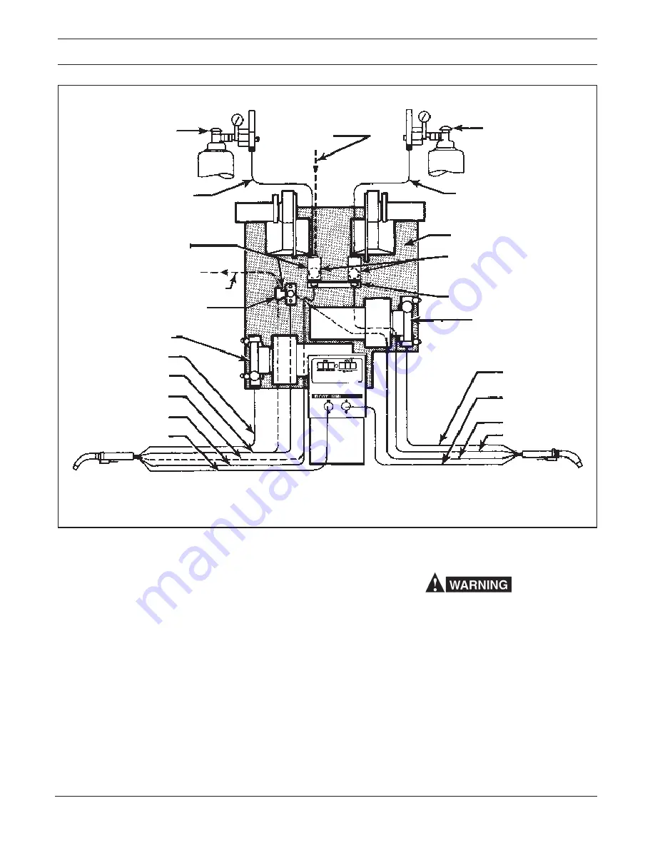
Fig. 2-1 - Torch and Service Interconnection diagram
RIGHT TORCH
MOTOR/ACC. SUPPORT
PLAN VIEW DUAL FDR.
GAS HOSE
40V77
(12-1/2 FT.)
34V38
(25 FT.)
LEFT TORCH
(WATER COOLED)
TORCH SWITCH
TORCH GAS HOSE
TORCH WATER HOSE
TORCH POWER CABLE
TORCH CONDUIT
LEFT TORCH
MOTOR/ACC. SUPPORT
ADAPTOR - 45V11
WATER "DRAIN" HOSE - 40V76
(12-1/2 FT.)
GAS HOSE
40V77
(12-1/2 FT.)
34V38
(25 FT.)
REGULATOR/
FLOWMETER
WATER "IN" HOSE - 40V76
(12 1/2 FT.)
REGULATOR/
FLOWMETER
REF. CONTROL'S REAR
SUPPORT FRAME
TORCH CONDUIT
TORCH SWITCH
TORCH GAS HOSE
TORCH POWER CABLE
RIGHT TORCH
(AIR COOLED)
FRONT VIEW
CONTROL
Parts required when
using a Water Kit & Water
Cooled Torch.
WATER KIT - 994466
GAS SOLENOIDS
SECTION 2
INSTALLATION
2.1 GENERAL
Proper installation can contribute materially to the sat-
isfactory and trouble-free operation of the wire feeder.
It is suggested that each step in this section be carefully
studied and followed as closely as possible.
After checking to be sure you have all required compo-
nents and accessories (see Section 1), proceed as
follows (with reference to Figs. 2-1 & 2-2, Interconnec-
tion Diagrams):
To avoid possible lethal shock make sure that all
power to the Digimig is OFF before making any
welding/control cable and or accessory connec-
tions on this unit. Do this by "locking-open" the
input line disconnect switch to the power source.
2.2 CONNECTIONS
A. Hose And Electrical Connections
Connect shielding gas and water (if used) supply hoses
as shown in Fig. 2-1. Connect the control cable assem-
bly (J1) from the Digimig’s rear panel to the power
source as shown in Fig. 2-2.
Содержание Digimig Dual
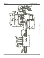
Страница 21: ...21 SECTION 4 TROUBLESHOOTING Fig 4 1 Schematic Diagram Dual Digimig 30914 L ...
Страница 22: ......
Страница 29: ...29 NOTES ...
Страница 30: ...30 NOTES ...


