10
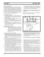
B. Torch Connections
Attach torch gas hose to gas connections. Plug in torch
switch cables and lock by twisting. After inserting con-
duit liner (if used) and attaching wire outlet guide of
correct size, connect wire feed conduit to welding head
clamp and lock in place. Attach water hose (if used) to
wire feeder. Connect torch power cables to power
source, or to power cable adaptor block (with a second
cable from that stud to the power source).
C. Installing Feed Roll
1. Release the clapper on the accessory support as-
sembly (Figure 6-5) by disengaging the retainer from
the clapper fork.
2. Remove thumbscrew, belleville washer, and flat
washer from the feed roll shaft.
3. Slip the feed roll on the shaft, engaging the key. Be
sure to observe this “THIS SIDE OUT” marking on the
feedroll.
4. Reassemble flatwasher, belleville washer, and thumb
screw, tightening screw sufficiently to eliminate all
end play from the feed roll.
D. Installing Spool Of Wire
CAUTION: Make sure safety glasses are worn when
clipping wire off at the spool or at the end of
the torch - serious eye injury can result due
to the springiness of the wire which quickly
unravels, or a cut wire end which may shoot
across the room.
1. Remove “hairpin” clip from spindle.
2. Position the spool of wire so that when it is placed on
the spindle, wire will be drawn to the feed roll from the
bottom of the spool. The spool should be held so that
the index hole on the back will engage the lug on the
spindle.
3. Slide the spool onto the spindle until it engages the
lug. Lock in place with the hairpin clip.
4. Loosen the brake screw in the center of the spindle
hub, then tighten it just enough to prevent coasting of
the spool when wire is drawn from it. Too much
pressure will load the wire feed motor unnecessarily.
Too little pressure will permit the spool to over-run,
causing the wire to kink and tangle.
5. Thread the wire on to the accessory support assem-
bly as described in E, following.
6. When wire coils are to be used instead of spools,
mount wire reel on spindle as through it were a spool
(see 1 and 3 above). Remove thumbnuts and cover
plate from reel. Remove coil from its package, but do
not remove its binding wires. Slide coil onto reel so
that wire will be drawn from bottom of coil (starting
J2
J1
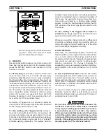
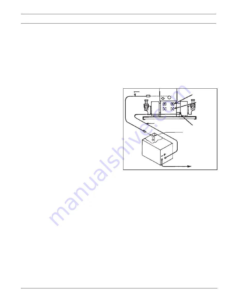
TYPICAL POWER
SOURCE HOOKUP
† ESAB will not honor the warranty on Digimigs that are used with non-
ESAB manufactured interconnect cables and sustain damage that
in ESAB’s opinion is caused by these cables. For a listing of the
proper J1 cables available refer to Section 1.4.
* 4/0 welding cables (customer supplied) are set-up for DCRP (NEG.
TO WORK) operation.
Fig. 2-2. Welding and Control Interconnection Diagram
1. Round off the free end of the welding wire with a file.
2. Release the clapper and unscrew the pressure ad-
justing knob until the pressure spring is free.
3. Thread the wire through the inlet and outlet guides of
the accessory support, and 3 or 4 inches into the
torch conduit.
4. Engage the clapper making sure the wire is held in
the feed roll groove.
5. Tighten the pressure adjusting knob until the wire is
firmly against the feed roll - do not overtighten. The
spring pressure applied should be the minimum
required to provide positive, nonslip wire feed. Too
little pressure will result in wire slippage while exces-
sive pressure will scar and deform the wire. Further
end for a coil is always the outer end). Replace reel
cover plate and thumbnuts. Cut off coil tie wires and
any kinked wire. Then adjust brakescrew and thread
wire to torch as covered in 4 and 5 above.
E. Adjusting The Accessory Support Assembly (See
Fig. 6-5).
When a new wire size or type is to be used, set the
pressure roll adjustment as follows:
SECTION 2
INSTALLATION
TO WORK*
RECPT.
4/0 WELDING CABLE*
OPT. WATER
ADAPTOR
POWER CABLE
ADAPTOR
J1 CABLE †
GSV'S
Содержание Digimig Dual
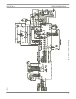
Страница 21: ...21 SECTION 4 TROUBLESHOOTING Fig 4 1 Schematic Diagram Dual Digimig 30914 L ...
Страница 22: ......
Страница 29: ...29 NOTES ...
Страница 30: ...30 NOTES ...


